Black Box MWU2000-X21 LNA-10 Cable Connection Diagram, Installing the AL-1 Lightning Arrestor

Models: MWU2000-G703 MWU2000-X21 MWU2000-V35

1 132
Download 132 pages 12 Kb
Page 31
Image 31

2.048Mbps Wireless Modem

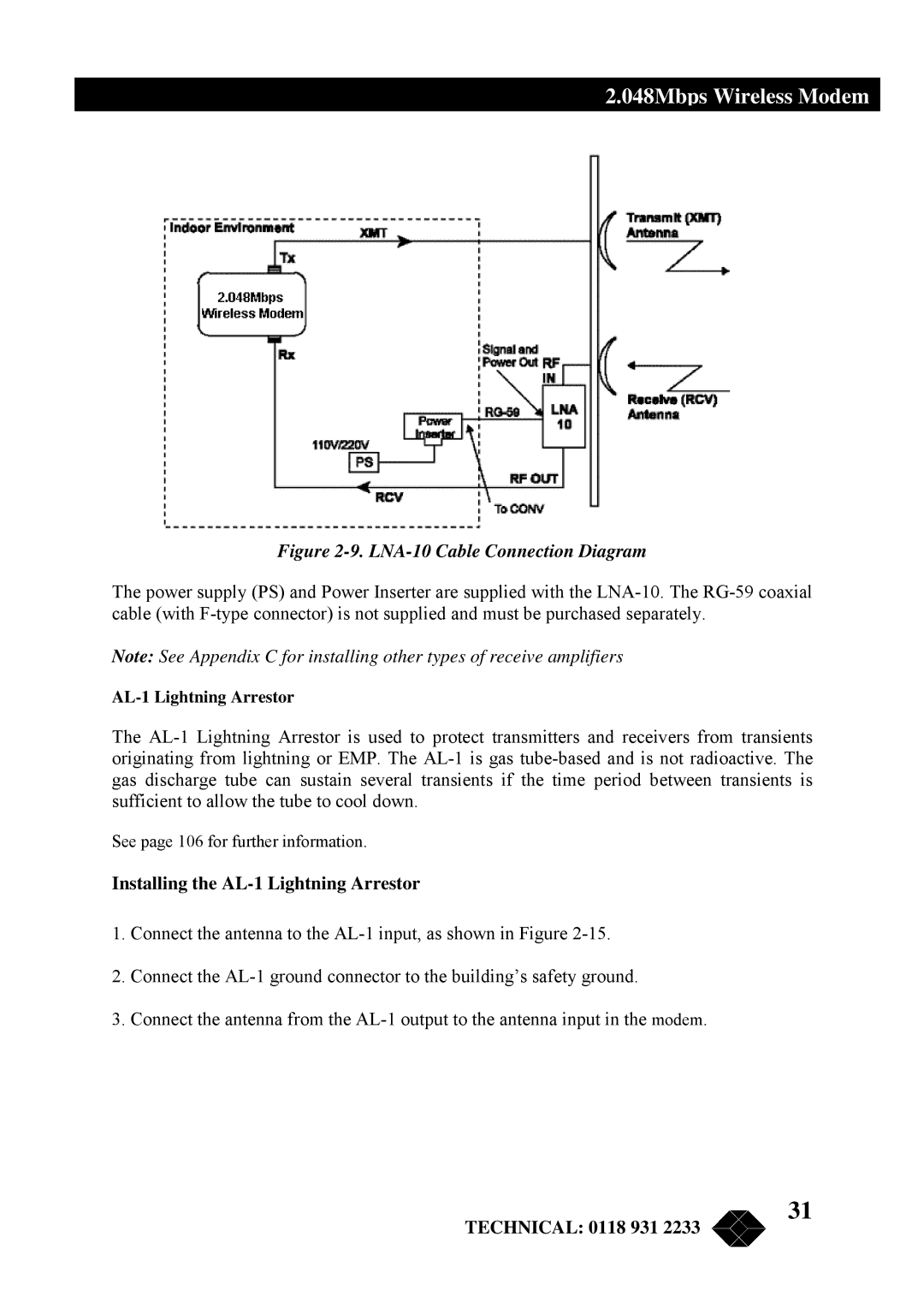
Figure 2-9. LNA-10 Cable Connection Diagram

The power supply (PS) and Power Inserter are supplied with the LNA-10. The RG-59 coaxial cable (with F-type connector) is not supplied and must be purchased separately.

Note: See Appendix C for installing other types of receive amplifiers

AL-1 Lightning Arrestor

The AL-1 Lightning Arrestor is used to protect transmitters and receivers from transients originating from lightning or EMP. The AL-1 is gas tube-based and is not radioactive. The gas discharge tube can sustain several transients if the time period between transients is sufficient to allow the tube to cool down.

See page 106 for further information.

Installing the AL-1 Lightning Arrestor

1.Connect the antenna to the AL-1 input, as shown in Figure 2-15.

2.Connect the AL-1 ground connector to the building’s safety ground.

3.Connect the antenna from the AL-1 output to the antenna input in the modem.

TECHNICAL: 0118 931 2233

31

Page 31
Image 31
Black Box MWU2000-X21, MWU2000-G703, MWU2000-V35 LNA-10 Cable Connection Diagram, Installing the AL-1 Lightning Arrestor