2.048Mbps Wireless Modem
To activate the front panel LEDs:
1.If the LEDs are not lit, loosen the screws on the
2.Tighten the screws on the
Step 3 – Fine tuning the adjustment of the antenna using RSSI Measurement
The RSSI (Receive Signal Strength Indicator) enables to
The RSSI value can be viewed using the local monitor, as described on page 72. The RSSI per channel feature displays in graphic format the strength of the received signal on each of the RF channels in use. The modem also enables to collect a measurement of the average RSSI using a DVM (digital voltmeter) connected to the RSSI test pin in the rear panel of the unit. The measured DC voltage is relative to the RSSI value as indicated in Figure
The RSSI measurement (with DVM or monitor) indicates the strength of reception. In order to maximize the reception strength, the receive antenna and the transmit antenna on the remote site of the link must be aligned facing each other until maximum signal quality is obtained. This procedure should be repeated on the modems on both sides of the link.
Note: The RSSI measurement indicates the strength of received signal in the 2.4
⇒To
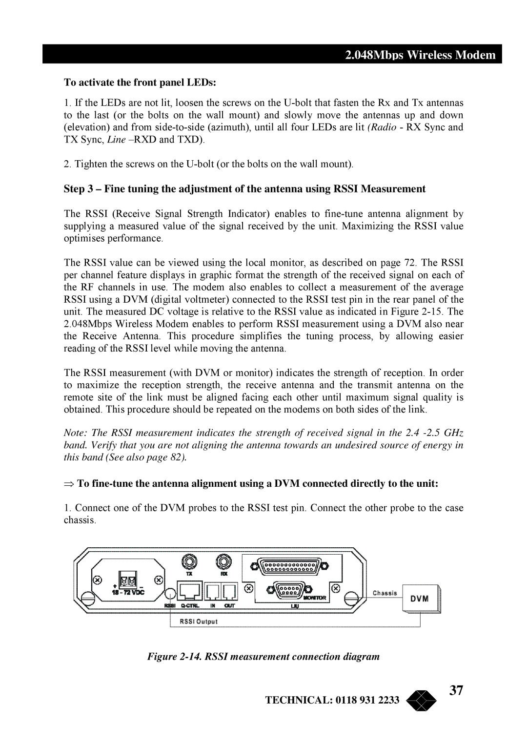
1.Connect one of the DVM probes to the RSSI test pin. Connect the other probe to the case chassis.
Figure 2-14. RSSI measurement connection diagram
TECHNICAL: 0118 931 2233
37