2.048Mbps Wireless Modem
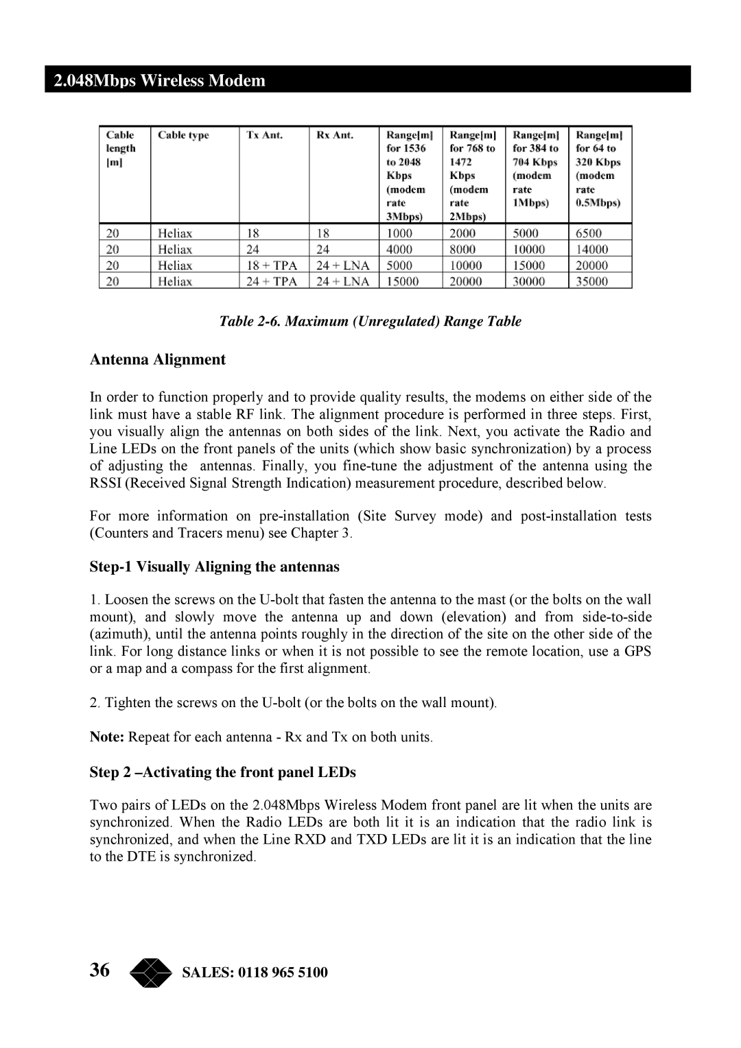
Table 2-6. Maximum (Unregulated) Range Table
Antenna Alignment
In order to function properly and to provide quality results, the modems on either side of the link must have a stable RF link. The alignment procedure is performed in three steps. First, you visually align the antennas on both sides of the link. Next, you activate the Radio and Line LEDs on the front panels of the units (which show basic synchronization) by a process of adjusting the antennas. Finally, you
For more information on
Step-1 Visually Aligning the antennas
1.Loosen the screws on the
2.Tighten the screws on the
Note: Repeat for each antenna - Rx and Tx on both units.
Step 2 –Activating the front panel LEDs
Two pairs of LEDs on the 2.048Mbps Wireless Modem front panel are lit when the units are synchronized. When the Radio LEDs are both lit it is an indication that the radio link is synchronized, and when the Line RXD and TXD LEDs are lit it is an indication that the line to the DTE is synchronized.
36 | SALES: 0118 965 5100 |