LOOP START
POSITION
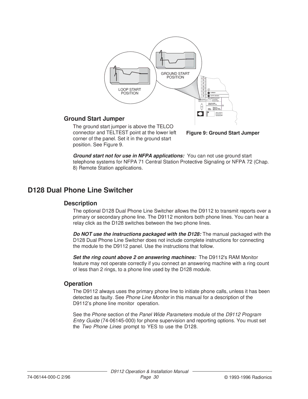
Ground Start Jumper
GROUND START
POSITION
8 |
|
|
9 | COMMON | |
10 | EARTH GROUND | |
LINE SNIFFER SELECT | ||
|
| Loop Start |
|
| Ground Start |
TELCO CORD | ||
MODEL No. D161 | ||
|
| RED |
|
| Requires |
GROUND Optional Relay | ||
START | Model No. D136 | |
M |
The ground start jumper is above the TELCO
connector and TELTEST point at the lower left Figure 9: Ground Start Jumper corner of the panel. Set it in the ground start
position. See Figure 9.
Ground start not for use in NFPA applications: You can not use ground start telephone systems for NFPA 71 Central Station Protective Signaling or NFPA 72 (Chap. 8) Remote Station applications.
D128 Dual Phone Line Switcher
Description
The optional D128 Dual Phone Line Switcher allows the D9112 to transmit reports over a primary or secondary phone line. The D9112 monitors both phone lines. You can hear a relay click as the D128 switches between the two phone lines.
Do NOT use the instructions packaged with the D128: The manual packaged with the D128 Dual Phone Line Switcher does not include complete instructions for connecting the module to the D9112 panel. Use the instructions that follow.
Set the ring count above 2 on answering machines: The D9112's RAM Monitor feature may not operate correctly if you connect an answering machine with a ring count of less than 2 rings, to a phone line used by the D128 module.
Operation
The D9112 always uses the primary phone line to initiate phone calls, unless it has been detected as faulty. See Phone Line Monitor in this manual for a description of the D9112’s phone line monitor operation.
See the Phone section of the Panel Wide Parameters module of the D9112 Program Entry Guide
| D9112 Operation & Installation Manual |
|
Page 30 | © |