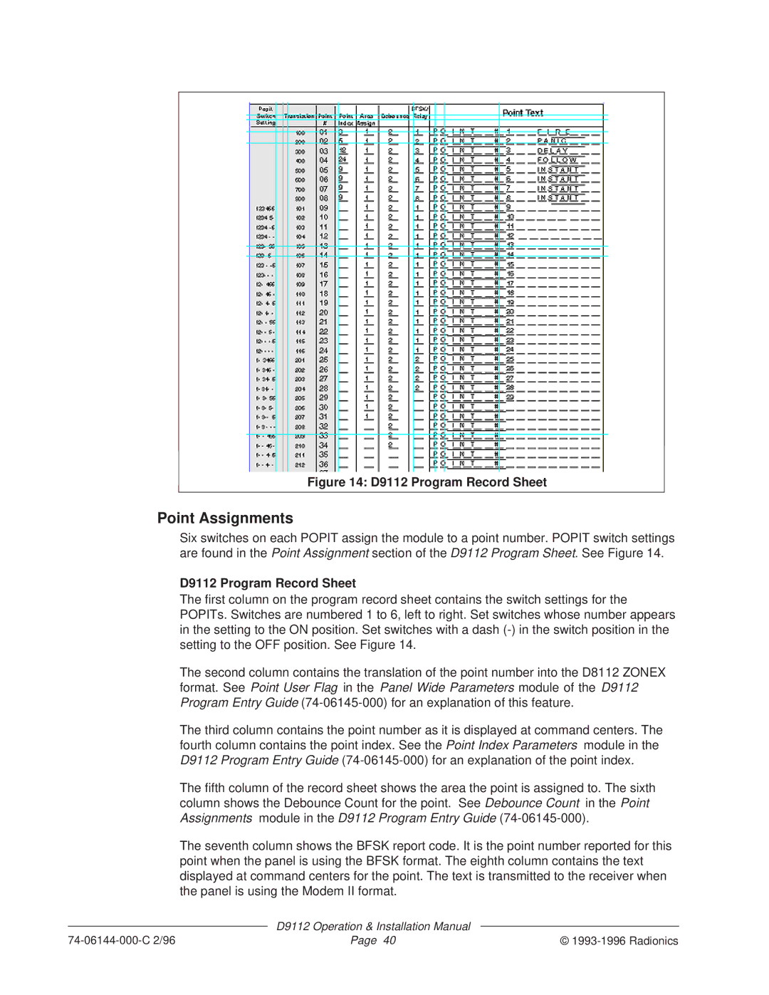
Figure 14: D9112 Program Record Sheet
Point Assignments
Six switches on each POPIT assign the module to a point number. POPIT switch settings are found in the Point Assignment section of the D9112 Program Sheet. See Figure 14.
D9112 Program Record Sheet
The first column on the program record sheet contains the switch settings for the POPITs. Switches are numbered 1 to 6, left to right. Set switches whose number appears in the setting to the ON position. Set switches with a dash
The second column contains the translation of the point number into the D8112 ZONEX format. See Point User Flag in the Panel Wide Parameters module of the D9112 Program Entry Guide
The third column contains the point number as it is displayed at command centers. The fourth column contains the point index. See the Point Index Parameters module in the D9112 Program Entry Guide
The fifth column of the record sheet shows the area the point is assigned to. The sixth column shows the Debounce Count for the point. See Debounce Count in the Point Assignments module in the D9112 Program Entry Guide
The seventh column shows the BFSK report code. It is the point number reported for this point when the panel is using the BFSK format. The eighth column contains the text displayed at command centers for the point. The text is transmitted to the receiver when the panel is using the Modem II format.
| D9112 Operation & Installation Manual |
|
Page 40 | © |