5.Disconnect the programmer.
6.Changes to some program parameters require a reset before they become effective.
Reset Recommended: Radionics recommends that you reset the panel after changing program parameters with the D5200 programmer.
If you locked down the reset pin in step 1, release it now to reset the panel. If you didn't lock the rest pin, momentarily close it now to reset the panel. See Figure 21.
Remember
Remember that the panel's
Programmer Access Reports
If you send a program to the panel, the panel sends a PROG ACCESS OK report ten seconds after you exit the handler or when you disconnect the programmer.
If you make 3 consecutive attempts to send or receive a program with an invalid DataLock code, the panel sends a PROG ACCESS BAD report. Successfully sending or receiving a program, or powering down the panel, resets the
counter.
POWER + 32
Accessory Connector (J2) | DATA BUS A | 31 | |
| |||
| DATA BUS B | 30 | |
|
| ||
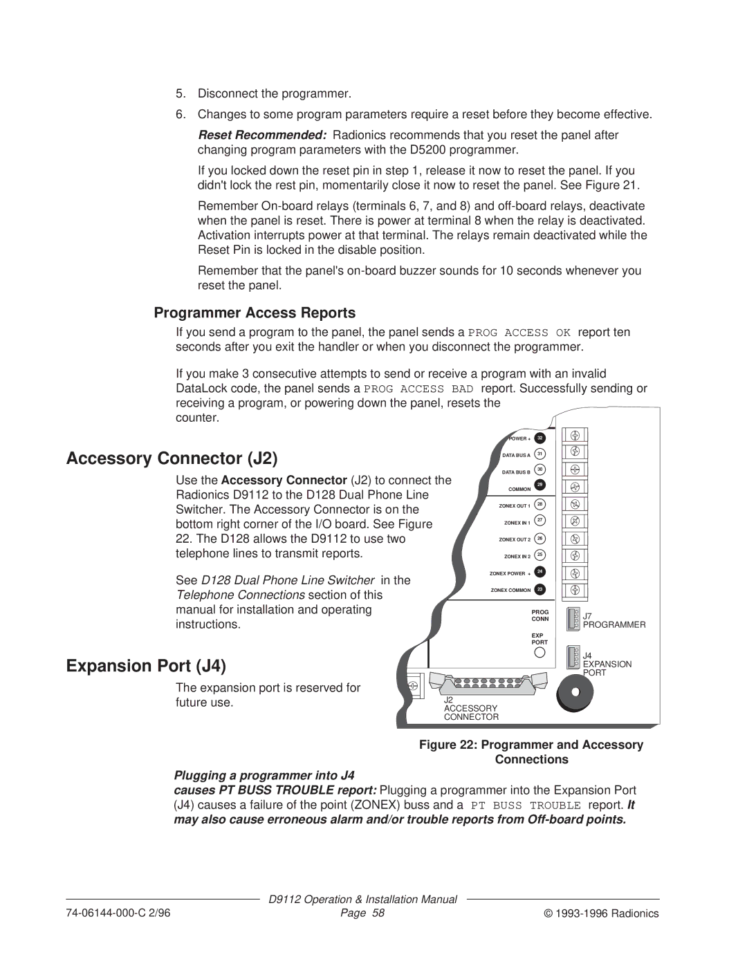
Use the Accessory Connector (J2) to connect the | 29 | ||
Radionics D9112 to the D128 Dual Phone Line | COMMON |
| |
| 28 | ||
Switcher. The Accessory Connector is on the | ZONEX OUT 1 | ||
| |||
|
| ||
bottom right corner of the I/O board. See Figure | ZONEX IN 1 | 27 | |
| |||
22. The D128 allows the D9112 to use two | ZONEX OUT 2 | 26 | |
|
| ||
telephone lines to transmit reports. | ZONEX IN 2 | 25 | |
See D128 Dual Phone Line Switcher in the | ZONEX POWER + | 24 | |
| |||
| 23 | ||
Telephone Connections section of this | ZONEX COMMON | ||
|
| ||
manual for installation and operating |
| PROG | |
instructions. |
| CONN | |
|
| ||
|
| EXP | |
|
| PORT | |
Expansion Port (J4) |
|
| |
The expansion port is reserved for |
|
| |
future use. | J2 |
| |
| ACCESSORY |
| |
CONNECTOR
J7 PROGRAMMER
J4 EXPANSION PORT
Figure 22: Programmer and Accessory
Connections
Plugging a programmer into J4
causes PT BUSS TROUBLE report: Plugging a programmer into the Expansion Port (J4) causes a failure of the point (ZONEX) buss and a PT BUSS TROUBLE report. It may also cause erroneous alarm and/or trouble reports from
| D9112 Operation & Installation Manual |
|
Page 58 | © |