SWITCHES 1 TO 6
D8125
POPEX
MODULE POINTS 9 - 71
![]() (+)
(+)
(+)
GND
OUT
IN
AUX
D8127
POPIT
DATA | 33K Ω E.O.L. DATA | |
RESISITOR | ||
|
| |
NEGATIVE |
POSITIVE (+) |
DATA EXPANSION LOOP
DATA
DATA
UP TO 63 POPITS
SWITCHES 1 TO 6
D8125
POPEX
MODULE POINTS 73 - 135
![]() (+)
(+)
(+)
GND
OUT
IN
AUX
DATA | 33K Ω E.O.L. DATA | |
RESISITOR | ||
NEGATIVE |
POSITIVE (+) |
DATA EXPANSION LOOP
DATA
DATA
UP TO 63 POPITS
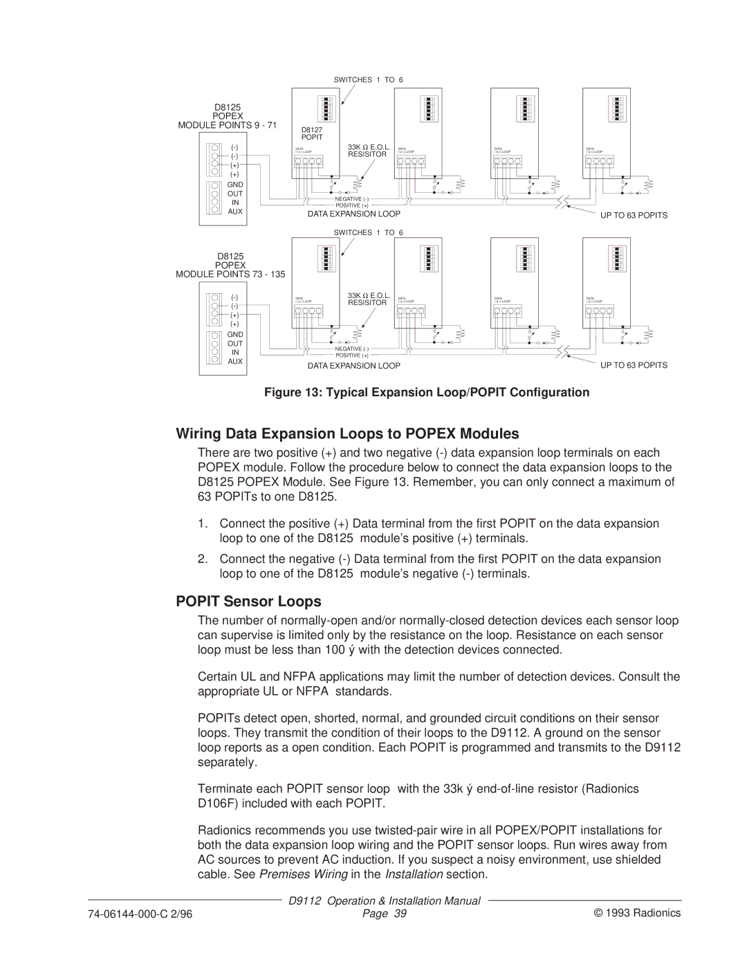
Figure 13: Typical Expansion Loop/POPIT Configuration
Wiring Data Expansion Loops to POPEX Modules
There are two positive (+) and two negative
1.Connect the positive (+) Data terminal from the first POPIT on the data expansion loop to one of the D8125 module’s positive (+) terminals.
2.Connect the negative
POPIT Sensor Loops
The number of
Certain UL and NFPA applications may limit the number of detection devices. Consult the appropriate UL or NFPA standards.
POPITs detect open, shorted, normal, and grounded circuit conditions on their sensor loops. They transmit the condition of their loops to the D9112. A ground on the sensor loop reports as a open condition. Each POPIT is programmed and transmits to the D9112 separately.
Terminate each POPIT sensor loop with the 33k ý
Radionics recommends you use
| D9112 | Operation & Installation Manual |
|
| © 1993 Radionics | ||
Page 39 | |||