Installation
Do not use the instructions packaged with the D8129: They do not include instructions for connecting the module to the D9112 panel. Follow the instructions below.
Set the switches on the OctoRelay before you install it in the enclosure. See Configuring the D8129 OctoRelay. You can install the OctoRelay in the enclosure with the D9112 (see Figure 2) or in an adjacent enclosure not more than 5 feet from the D9112. Use 16 to 22 AWG wire.
Follow the procedure below to install OctoRelays in the enclosure with the D9112.
1.Align the module with one of the mounting locations in the enclosure. See Figure 2.
2.Use the screws provided with the module to secure it in the enclosure.
Use the D137 Mounting Bracket to install OctoRelays in enclosures with no module mounting locations available.
Wiring Connections
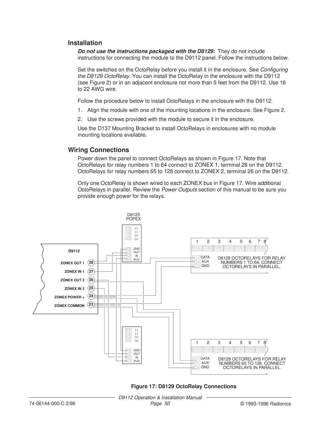
Power down the panel to connect OctoRelays as shown in Figure 17. Note that OctoRelays for relay numbers 1 to 64 connect to ZONEX 1, terminal 28 on the D9112. OctoRelays for relay numbers 65 to 128 connect to ZONEX 2, terminal 26 on the D9112.
Only one OctoRelay is shown wired to each ZONEX bus in Figure 17. Wire additional OctoRelays in parallel. Review the Power Outputs section of this manual to be sure you provide enough power for the relays.
D9112
ZONEX OUT 1 | 28 |
ZONEX IN 1 | 27 |
ZONEX OUT 2 | 26 |
ZONEX IN 2 | 25 |
ZONEX POWER + | 24 |
|
ZONEX COMMON 23
D8125
POPEX
(+)
(+)
GND
OUT
IN
AUX
(+)
(+)
GND
OUT
IN
AUX
1 2 3 4 5 6 7 8
DATA | D8129 OCTORELAYS FOR RELAY |
AUX | NUMBERS 1 TO 64. CONNECT |
GND | OCTORELAYS IN PARALLEL. |
1 | 2 | 3 | 4 | 5 | 6 | 7 | 8 |
| DATA | D8129 OCTORELAYS FOR RELAY | |||||
| AUX | NUMBERS 65 TO 128. CONNECT | |||||
| GND |
| OCTORELAYS IN PARALLEL. | ||||
Figure 17: D8129 OctoRelay Connections
| D9112 Operation & Installation Manual |
|
Page 50 | © |