| |
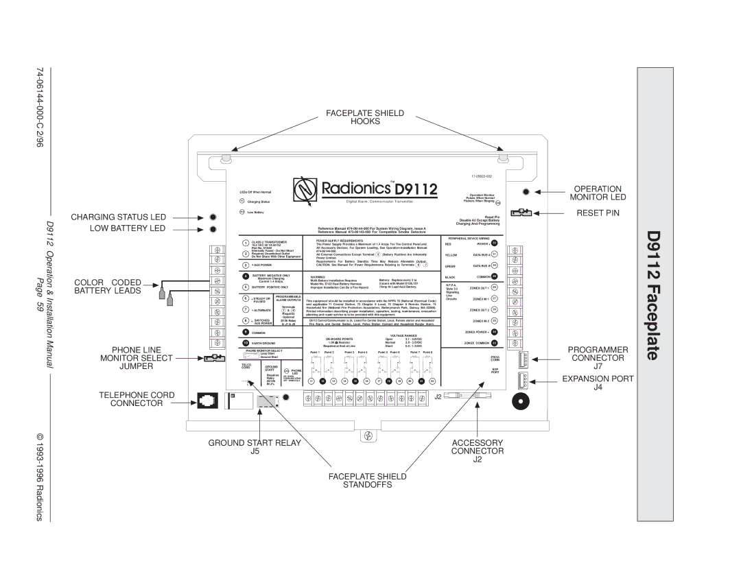
000- | FACEPLATE SHIELD |
C 2/96 | HOOKS |
|
|
|
|
| LEDs Off When Normal |
|
|
|
|
|
|
|
|
|
|
| D9112 | Operation Monitor | OPERATION | ||||||||
|
|
|
| YEL |
|
|
|
|
|
|
|
|
|
|
|
|
|
|
|
|
|
|
| Flickers When Ringing | MONITOR LED | |
|
|
|
|
|
|
|
|
|
|
|
|
|
|
|
|
|
|
|
|
|
|
|
| Pulses When Normal |
| |
|
|
|
|
| Charging Status |
|
|
|
|
| Digital Alarm, Communicator Transmitter |
|
|
|
| GRN |
| |||||||||
|
| CHARGING STATUS LED | RED | Low Battery |
|
|
|
|
|
|
|
|
|
|
|
|
|
|
|
|
|
| RESET PIN | |||
|
|
|
|
|
|
|
|
|
|
|
|
|
|
|
|
|
|
|
|
|
| Disable All Except Battery |
| |||
| D9112 |
|
|
|
|
|
|
|
|
|
|
|
|
|
|
|
|
|
|
|
|
|
| Reset Pin |
| |
|
|
|
| 1 | 16.5 VAC 40 VA 60 HZ |
|
| The Power Supply Provides a Maximum of 1.4 Amps For The Control Panel and | RED | POWER + |
|
| ||||||||||||||
|
| LOW BATTERY LED |
|
|
|
|
|
|
| Reference Manual | Charging And Programming |
| ||||||||||||||
|
|
|
|
|
|
|
|
|
|
| Reference Manual |
|
|
|
| |||||||||||
|
|
|
|
|
|
|
|
|
|
| POWER SUPPLY REQUIREMENTS |
|
|
|
|
|
| PERIPHERAL DEVICE WIRING |
|
| ||||||
|
|
|
|
|
| CLASS 2 TRANSFORMER |
|
|
|
|
|
|
|
|
| 32 |
| |||||||||
|
|
|
|
|
|
|
|
|
|
|
|
|
|
|
|
|
|
|
|
|
| |||||
| Operation& |
|
|
|
| Part No. D1640 |
|
|
| All Accessory Devices. For System Loading, See |
|
|
|
| ||||||||||||
Page | BATTERY LEADS |
| 2 | Internally Fused - Do Not Short |
|
|
|
|
|
|
|
|
|
|
| Line |
|
|
| |||||||
| Requires Unswitched Outlet |
| All External Connections Except Terminal | 5 | (Battery Positive) Are Inherently | DATA BUS A | 31 |
| ||||||||||||||||||
|
|
|
|
|
| Do Not Share With Other Equipment |
| YELLOW |
|
| ||||||||||||||||
|
|
|
|
|
|
| Power Limited. |
|
|
|
|
|
|
|
|
|
|
|
|
|
| |||||
|
|
|
|
|
|
|
|
|
|
|
|
|
|
|
|
|
|
|
|
|
|
|
|
| ||
|
|
|
|
|
| + AUX POWER |
|
|
| Requirements For Battery Standby Time May Reduce Allowable Output. |
|
|
|
| ||||||||||||
|
|
|
|
| 3 |
|
|
| CAUTION: See Manual For Power Requirements Relating to Terminals | 6 | 7 | GREEN | DATA BUS B | 30 |
| |||||||||||
|
|
|
|
| 4 |
| BATTERY NEGATIVE ONLY | WARNING! |
|
|
|
|
|
|
|
|
|
| BLACK | COMMON | 29 |
| ||||
|
| COLOR | CODED |
|
|
| Maximum Charging |
|
|
|
| Battery: Replace every 3 to |
|
|
| |||||||||||
|
|
|
|
| Current 1.4 Amps. |
|
|
|
|
|
|
| ||||||||||||||
|
|
| 5 |
| BATTERY POSITIVE ONLY | Model No. D122 Dual Battery Harness |
| 5 years with Model D126,12V |
| N.F.P.A. |
| 28 |
| |||||||||||||
|
|
|
|
|
| Improper Installation Can Be a Fire Hazard. | 7Amp Hr Lead Acid Battery. |
| Style 3.5 | ZONEX OUT 1 |
| |||||||||||||||
|
|
|
|
|
|
|
|
|
|
|
|
|
|
|
|
|
|
|
|
|
|
| Signaling |
|
|
|
59 | Installation |
|
|
| 6 | + STEADY OR | PROGRAMMABLE |
|
|
|
|
|
|
|
| VOLTAGE RANGES |
| Circuits | ZONEX IN 1 | 27 |
| |||||
|
|
| ALARM OUTPUTS |
|
|
|
|
|
|
|
|
|
| |||||||||||||
|
|
|
|
|
|
| PULSED | This equipment should be installed in accordance with the NFPA 70 (National Electrical Code) |
|
|
| |||||||||||||||
|
|
|
|
|
|
|
|
|
|
|
| |||||||||||||||
|
|
|
|
|
|
|
|
| Terminals | and applicable 71 Central Station, 72 Chapter 6 Local, 72 Chapter 8 Remote Station, 74 |
|
|
| |||||||||||||
|
|
|
|
| 7 | + ALTERNATE |
| Household fire (National Fire Protection Association, Batterymarch Park, Quincy, MA 02269). | ZONEX OUT 2 | 26 |
| |||||||||||||||
|
|
|
|
|
| 7 & 8 | Printed information describing proper installation, operation, testing, maintenance, evacuation |
| ||||||||||||||||||
|
|
|
|
|
|
|
|
| Requires | planning and repair service is to be provided with this equipment. |
|
|
|
|
|
|
| |||||||||
|
|
|
|
| 8 |
|
|
| Optional |
|
|
|
|
|
|
|
|
|
|
|
|
|
|
|
|
|
|
|
|
|
| + SWITCHED |
| D136 Relay | D9112 Control/Communicator is UL Listed For Central Station, Local, Remote station and Household | ZONEX IN 2 | 25 |
| |||||||||||||||
|
|
|
|
|
|
| AUX POWER |
| in J1 & J9 | Fire Alarm, | and Central | Station, | Local, | Police Station | Connect | ahd Household | Burglar Alarm. |
|
|
| ||||||
|
|
|
|
| 9 |
| COMMON |
|
|
|
|
|
|
|
|
|
|
|
|
|
|
|
| ZONEX POWER + | 24 |
|
| Manual |
|
|
|
|
|
|
|
|
|
|
|
|
|
| Open |
| 3.7 - 5.0VDC |
|
|
|
| ||||
|
|
|
| 10 |
| EARTH GROUND |
|
|
|
| 1.0K Ω Resistor |
|
|
|
| Normal | 2.0 - 3.0VDC |
| ZONEX COMMON | 23 |
| |||||
|
|
| PHONE LINE |
|
|
|
|
|
|
| Required at End of Line |
|
|
| Short |
| 0.0 - 1.3VDC |
|
|
| PROGRAMMER | |||||
|
|
|
|
|
| Loop Start |
|
| Point 1 | Point 2 | Point 3 | Point 4 | Point 5 Point 6 | Point 7 | Point 8 |
|
| |||||||||
|
| MONITOR SELECT |
| PHONE MONITOR SELECT |
|
|
|
|
|
|
|
|
|
|
|
|
|
|
|
| CONNECTOR | |||||
|
|
|
|
| Ground Start |
|
|
|
|
|
|
|
|
|
|
|
|
|
|
|
| CONN | ||||
|
|
| JUMPER |
|
|
|
|
|
|
|
|
|
|
|
|
|
|
|
|
|
|
| PROG | J7 | ||
|
|
| CORD |
| GROUND |
|
|
|
|
|
|
|
|
|
|
|
|
|
|
|
| EXP | ||||
|
|
|
| TELCO |
|
|
|
|
|
|
|
|
|
|
|
|
|
|
|
|
|
|
|
| ||
|
|
|
|
|
|
| START |
| RED PHONE |
|
|
|
|
|
|
|
|
|
|
|
|
|
|
| PORT |
|
|
|
|
|
|
|
| Requires | LED |
|
|
|
|
|
|
|
|
|
|
|
|
|
|
|
| ||
|
|
|
|
|
|
|
|
|
|
|
|
|
|
|
|
|
|
|
|
|
|
| EXPANSION PORT | |||
|
|
|
| MODEL | ON WHEN | 11 | 12 | 13 | 14 | 15 |
| 16 | 17 | 18 | 19 | 20 |
| 21 | 22 |
|
| |||||
|
|
|
| #D136 |
| COMMUNICATING |
|
|
|
| ||||||||||||||||
|
|
|
|
|
|
| Relay |
|
|
|
|
|
|
|
|
|
|
|
|
|
|
|
|
|
| |
|
|
|
|
|
|
|
|
| OFF WHEN IDLE |
|
|
|
|
|
|
|
|
|
|
|
|
|
|
|
|
|
|
|
|
| D161 |
| IN J% |
|
|
|
|
|
|
|
|
|
|
|
|
|
|
|
|
|
| J4 | |
|
| TELEPHONE CORD |
|
|
|
|
|
|
|
|
|
|
|
|
|
|
|
|
|
|
|
|
|
| ||
|
| M |
|
|
|
|
|
|
|
|
|
|
|
|
|
|
|
|
|
| J2 |
|
|
| ||
|
|
| CONNECTOR |
|
|
|
|
|
|
|
|
|
|
|
|
|
|
|
|
|
|
|
|
|
|
|
© | GROUND START RELAY | ACCESSORY | |
J5 | CONNECTOR | ||
|
| J2 | |
|
| FACEPLATE SHIELD | |
Radionics |
| STANDOFFS | |
|
|
D9112 Faceplate