D128 Status LEDs
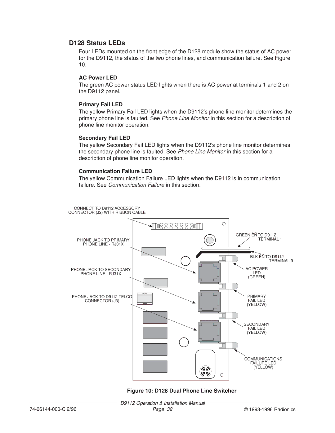
Four LEDs mounted on the front edge of the D128 module show the status of AC power for the D9112, the status of the two phone lines, and communication failure. See Figure 10.
AC Power LED
The green AC power status LED lights when there is AC power at terminals 1 and 2 on the D9112 panel.
Primary Fail LED
The yellow Primary Fail LED lights when the D9112’s phone line monitor determines the primary phone line is faulted. See Phone Line Monitor in this section for a description of phone line monitor operation.
Secondary Fail LED
The yellow Secondary Fail LED lights when the D9112’s phone line monitor determines the secondary phone line is faulted. See Phone Line Monitor in this section for a description of phone line monitor operation.
Communication Failure LED
The yellow Communication Failure LED lights when the D9112 is in communication failure. See Communication Failure in this section.
CONNECT TO D9112 ACCESSORY
CONNECTOR (J2) WITH RIBBON CABLE
| GREEN ÊÑ TO D9112 |
PHONE JACK TO PRIMARY | TERMINAL 1 |
PHONE LINE - RJ31X |
|
| BLK ÊÑ TO D9112 |
| TERMINAL 9 |
PHONE JACK TO SECONDARY | AC POWER |
PHONE LINE - RJ31X | LED |
| (GREEN) |
PHONE JACK TO D9112 TELCO | PRIMARY |
CONNECTOR (J3) | FAIL LED |
| (YELLOW) |
| SECONDARY |
| FAIL LED |
| (YELLOW) |
| COMMUNICATIONS |
| FAILURE LED |
| (YELLOW) |
Figure 10: D128 Dual Phone Line Switcher
D9112 Operation & Installation Manual
| Page 32 | © |