Programmable Power Outputs | Terminals | 6 | 7 | 8 |
Programming
The power outputs at terminals 6, 7, and 8 are programmed as relays A, B, and C. All relays are programmed in the Relays module of the program. Relays are assigned a relay type, Fire Bell for example, when they are assigned to an area. Relays can be assigned to one or more areas.
The Radionics defaults set relay A (terminal 6) as an Alarm Bell output, relay B (terminal
7)as a Fire Bell output, and relay C (terminal 8) as a Verification/Reset output. The D9112 Program Entry Guide
See the Bell Parameters section of the program to set the Fire Bell, Alarm Bell output responses for relays. Four annunciation patterns: Steady, Pulsed, California Standard, and Temporal Code 3 are available.
Unexpected Output at Terminals 6, 7 and 8: If terminals 6, 7, and 8 don’t provide the output you expect:
•Check the programming for relays A, B, and C in the Relays module of the program.
•Check the Bell Parameters section of the program to verify the Alarm and Fire Bell responses are programmed for the duration and pattern you expect.
•Check the Point Assignments to verify each point is programmed for the local response you expect.
Optional Relays Required
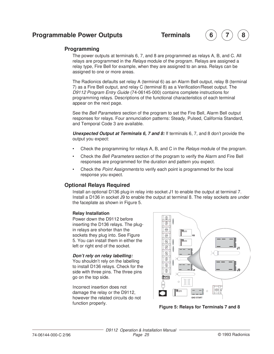
Install an optional D136
Relay Installation
Power down the D9112 before inserting the D136 relays. The plug- in relays are shorter than the sockets they plug into. See Figure
5.You can install them in either the left or right end of the socket.
Don’t rely on relay labelling: You shouldn’t rely on the labelling to install D136 relays. Check for the side with three pins. The three pins go on the top side.
Incorrect insertion does not damage the relay or the D9112, however the related circuits do not function properly.
M Aromat
K6
M Aromat
J1 |
J9 |
M Aromat |
GND START
J1 |
J9 |
Figure 5: Relays for Terminals 7 and 8
| D9112 | Operation & Installation Manual |
|
| © 1993 Radionics | ||
Page 25 | |||