System Chart
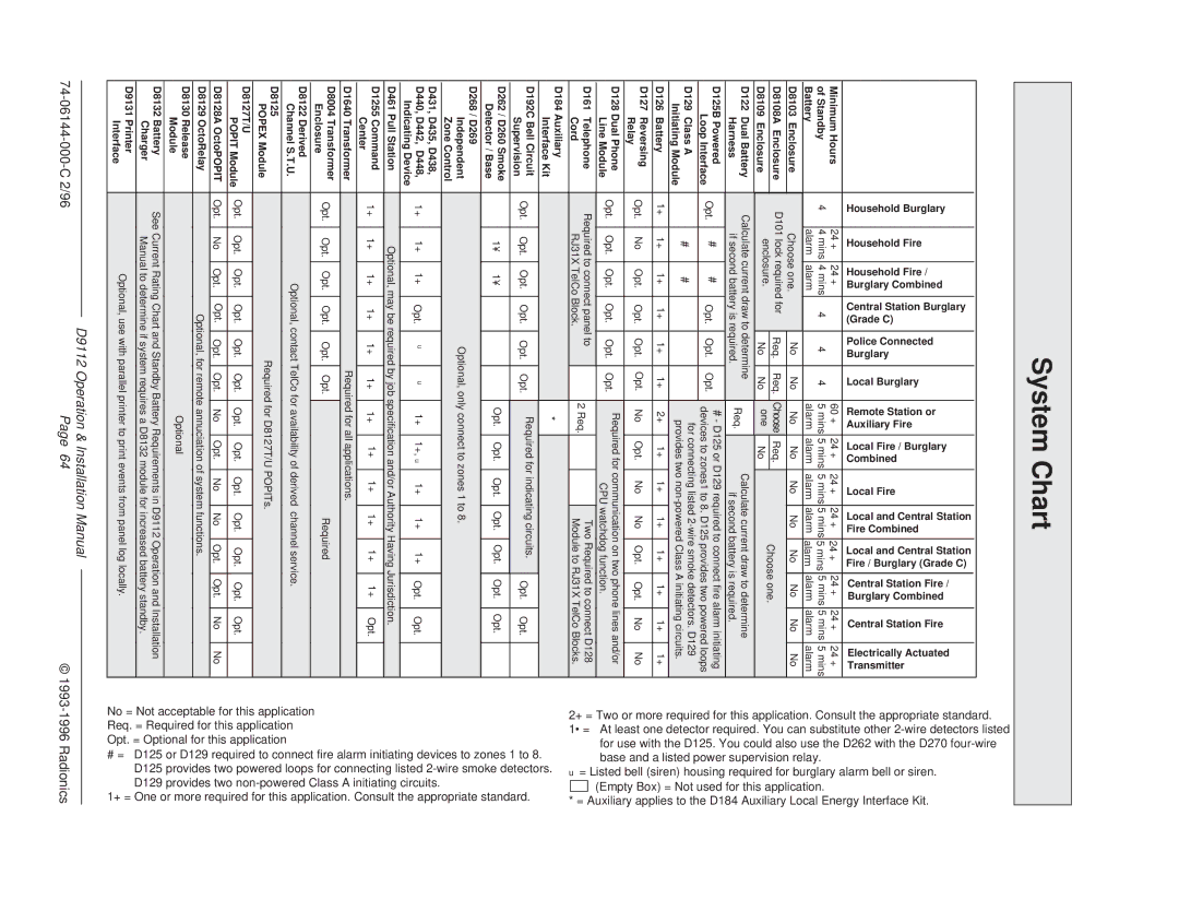
| Household Burglary | Household Fire | Household Fire / Burglary Combined | Central Station Burglary | (Grade C) | Police Connected Burglary | Local Burglary | Remote Station or | Auxiliary Fire | Local Fire / Burglary | Combined | Local Fire | Local and Central Station Fire Combined | Local and Central Station Fire / Burglary (Grade C) | Central Station Fire / Burglary Combined | Central Station Fire | Electrically Actuated Transmitter |
Minimum Hours |
| 24 + | 24 + |
|
|
|
| 60 | + | 24 | + | 24 + | 24 + | 24 + | 24 + | 24 + | 24 + |
of Standby | 4 | 4 mins | 4 mins |
| 4 | 4 | 4 | 5 mins 5 mins | 5 mins 5 mins 5 mins 5 mins 5 mins | 5 mins | |||||||
Battery |
| alarm | alarm |
|
|
|
| alarm | alarm | alarm alarm alarm alarm alarm | alarm | ||||||
D8103 Enclosure |
| Choose one. |
|
| No | No | No | No | No | No | No | No | No | No | |||
D8108A Enclosure | D101 lock required for | Req. | Req. Choose | Req. |
|
| Choose one. |
|
| ||||||||
D8109 Enclosure |
| enclosure. |
|
| No | No | one | No |
|
|
|
| |||||
|
|
|
|
|
|
|
|
| |||||||||
|
|
|
|
|
|
|
|
|
|
|
|
| |||||
| D122 Dual Battery | Calculate current draw to determine |
| Req. |
| Calculate current draw to determine |
| |||||||||||
| Harness |
| if second battery is required. |
|
|
| if second battery is required. |
| ||||||||||
|
|
|
|
|
|
| ||||||||||||
| D125B Powered | Opt. | # | # | Opt. | Opt. | Opt. |
| # - D125 or D129 required to connect fire alarm initiating | |||||||||
| Loop Interface |
| devices to zones1 to 8. D125 provides two powered loops | |||||||||||||||
|
|
|
|
|
|
|
| |||||||||||
| D129 Class A |
| # | # |
|
|
|
| for connecting listed | |||||||||
|
|
|
|
|
| provides two | ||||||||||||
| Initiating Module |
|
|
|
|
|
|
| ||||||||||
| D126 Battery | 1+ | 1+ | 1+ | 1+ | 1+ | 1+ | 2+ | 1+ | 1+ |
| 1+ | 1+ | 1+ | 1+ | 1+ | ||
| D127 Reversing | Opt. | No | Opt. | Opt. | Opt. | Opt. |
| No | Opt. | No |
| No | Opt. | Opt. | No | No | |
| Relay |
|
| |||||||||||||||
|
|
|
|
|
|
|
|
|
|
|
|
|
|
|
|
| ||
| D128 Dual Phone | Opt. | Opt. | Opt. | Opt. | Opt. | Opt. |
| Required for communication on two phone lines and/or | |||||||||
| Line Module |
|
|
| CPU watchdog function. |
|
| |||||||||||
|
|
|
|
|
|
|
|
|
|
|
| |||||||
| D161 Telephone | Required to connect panel to |
|
| 2 Req. |
|
|
| Two Required to connect D128 | |||||||||
| Cord |
| RJ31X TelCo Block. |
|
|
|
|
|
| Module to RJ31X TelCo Blocks. | ||||||||
|
|
|
|
|
|
|
|
| ||||||||||
| D184 Auxiliary |
|
|
|
|
|
| * |
|
|
|
|
|
|
|
| ||
| Interface Kit |
|
|
|
|
|
|
|
|
|
|
|
|
|
| |||
|
|
|
|
|
|
|
|
|
|
|
|
|
|
|
|
| ||
| D192C Bell Circuit | Opt. | Opt. | Opt. | Opt. | Opt. | Opt. |
| Required for indicating circuits. | Opt. | Opt. |
| ||||||
| Supervision |
|
|
|
|
|
|
|
| |||||||||
|
|
|
|
|
|
|
|
|
|
|
|
|
|
|
|
| ||
| D262 / D260 Smoke |
| 1¥ | 1¥ |
|
|
|
| Opt. | Opt. | Opt. |
| Opt. | Opt. | Opt. | Opt. |
| |
| Detector / Base |
|
|
|
|
|
|
| ||||||||||
|
|
|
|
|
|
|
|
|
|
|
|
|
|
|
|
| ||
|
|
|
|
|
|
|
|
|
|
|
|
|
|
|
|
|
|
|
| D268 / D269 |
|
|
|
| Optional, only connect to zones 1 to 8. |
|
|
|
| ||||||||
| Independent |
|
|
|
|
|
|
|
| |||||||||
| Zone Control |
|
|
|
|
|
|
|
|
|
|
|
|
|
|
|
| |
| D431, D435, D438, | 1+ | 1+ | 1+ | Opt. |
|
| 1+ | 1+, ◆ | 1+ |
| 1+ | 1+ | Opt. | Opt. |
| ||
| D440, D442, D448, | ◆ | ◆ |
|
| |||||||||||||
| Indicating Device |
|
|
|
|
|
|
|
|
|
|
|
|
|
|
|
| |
| D461 Pull Station |
| Optional, may be required by job specification and/or Authority Having Jurisdiction. |
| ||||||||||||||
| D1255 Command | 1+ | 1+ | 1+ | 1+ | 1+ | 1+ | 1+ | 1+ | 1+ |
| 1+ | 1+ | 1+ | Opt. |
| ||
| Center |
|
| |||||||||||||||
|
|
|
|
|
|
|
|
|
|
|
|
|
|
|
|
| ||
| D1640 Transformer |
|
|
|
|
| Required for all applications. |
|
|
|
|
| ||||||
| D8004 Transformer | Opt. | Opt. | Opt. | Opt. | Opt. | Opt. |
|
|
|
|
| Required |
|
|
| ||
| Enclosure |
|
|
|
|
|
|
|
| |||||||||
|
|
|
|
|
|
|
|
|
|
|
|
|
|
|
|
| ||
| D8122 Derived |
|
| Optional, contact TelCo for availability of derived | channel service. |
|
| |||||||||||
| Channel S.T.U. |
|
|
|
| |||||||||||||
|
|
|
|
|
|
|
|
|
|
|
|
|
|
|
|
| ||
| D8125 |
|
|
|
| Required for D8127T/U POPITs. |
|
|
|
|
| |||||||
| POPEX Module |
|
|
|
|
|
|
|
|
| ||||||||
|
|
|
|
|
|
|
|
|
|
|
|
|
|
|
|
| ||
| D8127T/U | Opt. | Opt. | Opt. | Opt. | Opt. | Opt. |
| Opt. | Opt. | Opt. |
| Opt. | Opt. | Opt. | Opt. |
| |
| POPIT Module |
|
|
| ||||||||||||||
|
|
|
|
|
|
|
|
|
|
|
|
|
|
|
|
| ||
| D8128A OctoPOPIT | Opt. | No | Opt. | Opt. | Opt. | Opt. |
| No | Opt. | No |
| No | Opt. | Opt. | No | No | |
| D8129 OctoRelay |
|
|
| Optional, for remote annuciation of system functions. |
|
|
| ||||||||||
| D8130 Release |
|
|
|
|
|
|
|
| Optional |
|
|
|
|
|
|
| |
| Module |
|
|
|
|
|
|
|
|
|
|
|
|
|
| |||
|
|
|
|
|
|
|
|
|
|
|
|
|
|
|
|
| ||
| D8132 Battery |
| See Current Rating Chart and Standby Battery Requirements in D9112 Operation and Installation | |||||||||||||||
| Charger |
| Manual to determine if system requires a D8132 module for increased battery standby. |
| ||||||||||||||
| D9131 Printer |
|
| Optional, use with parallel printer to print events from panel log locally. |
|
| ||||||||||||
| Interface |
|
|
|
| |||||||||||||
|
|
|
|
|
|
|
|
|
|
|
|
|
|
|
|
| ||
|
|
|
|
|
|
|
|
|
|
|
|
|
|
|
|
|
|
|
2+ = Two or more required for this application. Consult the appropriate standard. | 1• = At least one detector required. You can substitute other | for use with the D125. You could also use the D262 with the D270 | base and a listed power supervision relay. | ◆ = Listed bell (siren) housing required for burglary alarm bell or siren. | (Empty Box) = Not used for this application. | |
|
|
| ||||
|
|
| to zones 1 to 8. | smoke detectors. |
|
|
Not acceptable for this application | = Required for this application | = Optional for this application | D125 or D129 required to connect fire alarm initiating devices | D125 provides two powered loops for connecting listed | D129 provides two | |
No = | Req. | Opt. | # = |
|
|
|
1+ = One or more required for this application. Consult the appropriate standard. * = Auxiliary applies to the D184 Auxiliary Local Energy Interface Kit.
| D9112 Operation & Installation Manual |
|
Page 64 | © |