On-Board Points
Description | Terminals | 11 to | 22 |
The D9112 panel provides eight
Point Sensor Loops
When wiring the
The number
Ground shunts cause missed alarms: The possibility of “ground shunts” increases significantly if you don’t install the resistor at the end of the line. If you install the resistor for points 1 to 8 before a detection device on the sensor loop and the loop becomes grounded after the resistor, any devices beyond the ground are “ground shunted”. Alarm or trouble conditions beyond the ground are not seen by the panel.
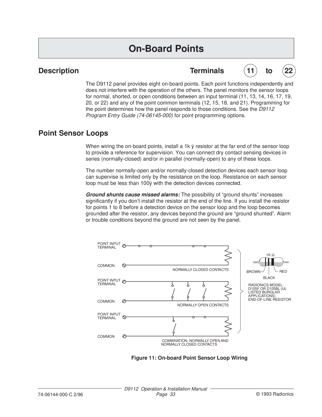
POINT INPUT
TERMINAL
COMMON
NORMALLY CLOSED CONTACTS
POINT INPUT
TERMINAL
COMMON
NORMALLY OPEN CONTACTS
POINT INPUT
TERMINAL
COMMON
COMBINATION: NORMALLY OPEN AND NORMALLY CLOSED CONTACTS
1K Ω
BROWN![]() RED BLACK
RED BLACK
RADIONICS MODEL D105F OR D105BL (UL
LISTED BURGLAR APPLICATIONS)
Figure 11: On-board Point Sensor Loop Wiring
| D9112 | Operation & Installation Manual |
|
| © 1993 Radionics | ||
Page 33 | |||