3.4 | Controls and displays on the camera module | |||
|
|
|
|
|
|
|
|
|
|
|
|
|
|
|
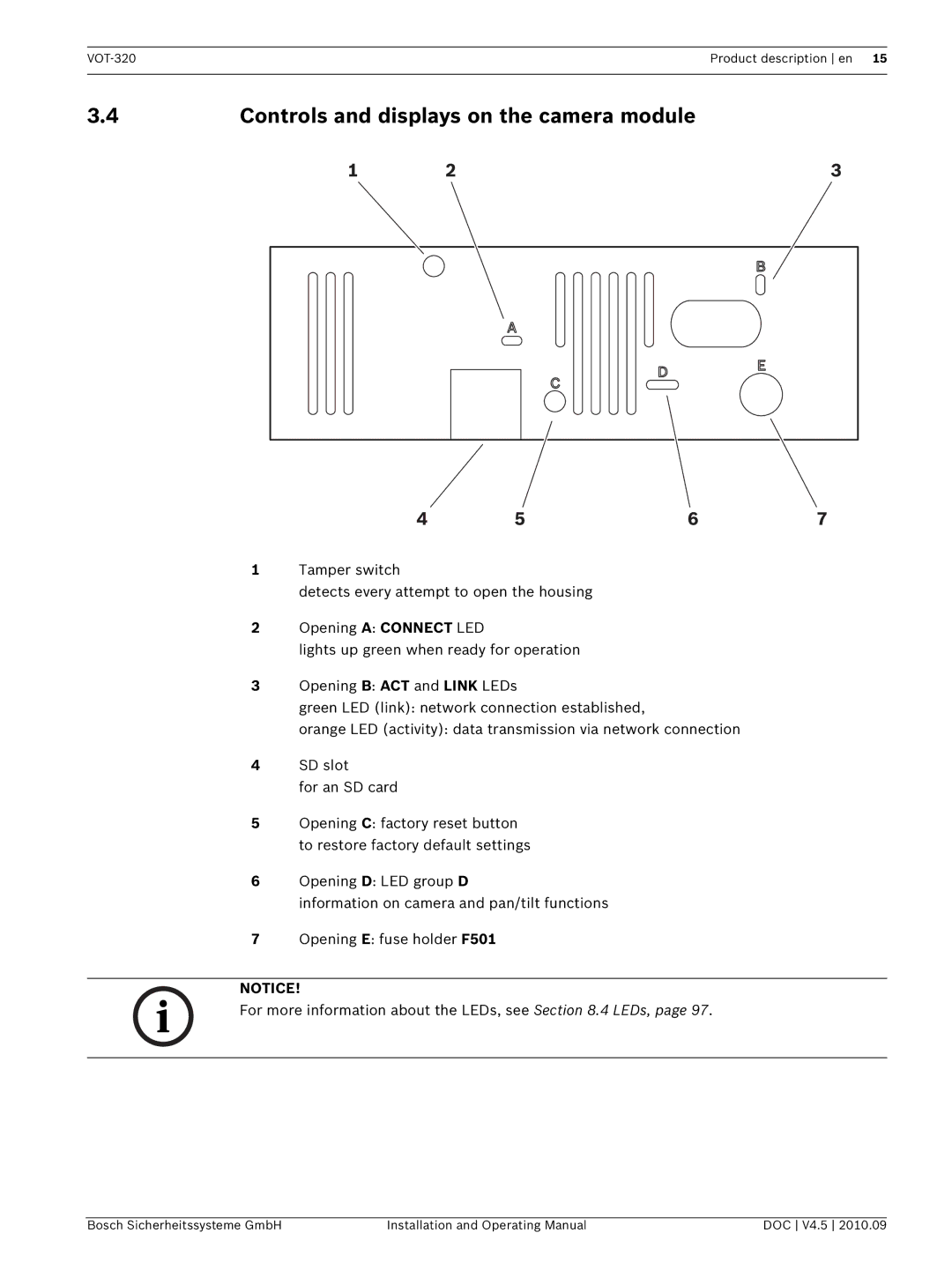
1Tamper switch
detects every attempt to open the housing
2Opening A: CONNECT LED
lights up green when ready for operation
3Opening B: ACT and LINK LEDs
green LED (link): network connection established,
orange LED (activity): data transmission via network connection
4SD slot
for an SD card
5Opening C: factory reset button to restore factory default settings
6Opening D: LED group D
information on camera and pan/tilt functions
7Opening E: fuse holder F501
NOTICE!
For more information about the LEDs, see Section 8.4 LEDs, page 97.
Bosch Sicherheitssysteme GmbH | Installation and Operating Manual | DOC V4.5 2010.09 |
