a30-5284


CB2


A2

SW2

MBB


TB4


5.2 AMPS

ORN


ORN


ORN

C2


5


J10A


B2


1

RED


1


2


BLK


2


BLU


3 RED


RLY 11


GRA


3


4


4


5


5


6 RED


PNK


RLY 9


6


7


7


8


8


RLY 10


9


ORN


9


1


HPS-B


J10B


BLU


10

BLK


BLK

BLU


RLY 5


2


VIO


11


3


12


RLY 6


4


PNK


13


5


TB4


RED


14


4


6


15


7 RED


RLY 7


16


RED


8


17


9


18


10 RED


RLY 8


19


ORN


11


HPS-A


20

BLK

BLK


BLK

BLK


12


RLY 1


21


ORN


13


22


14


RLY 2


23


GRA


15


24


16


RLY 3


25


VIO


17


26


TAN


18


RED


RLY 4


27


LVT


HEAT

J12


6


20

6


GRA


6


5


19

7


GRA


5


4


4

J6


3


ALMR

HR


3


VIO

2


BR


2


BRN

1


HEAT/BOILER FIELD

1


INSTALLED WIRING


CB1


3.2 AMPS


TB4


RED


4


TRAN1


TB1


RED


SEE NOTE 10


TB4

RED


BRN


MBB J1-2


PL1-3


PL1-4


RED

7


RED


XF

FU3

X1

SECONDARY 24V

X2


BRN


BRN


UPC GND

RED

RED

T2

MP-A1 T1

BRN

BRN


GRN/YEL


BRN


CWFS 3


PL1-7


SEE NOTE 11

PL1-8


BRN

A2

CB1


RED

RED

T2

MP-A2 T1

BRN

BRN


BRN


LVT J12-5


SEE NOTE 12


C

BRN

A2

CHC


PL2-3


PL2-4


BRN

A2

CA1

RED

RED

T2

MP-B1 T1

BRN

BRN


GRA

GRA


BRN


BRN


BRN

A2

CWP1


PL2-7


SEE NOTE 13

PL2-8


MLV-A


RED

RED

T2

MP-B2 T1

BRN

BRN


MLV ACCSY


BRN


PNK

A1

FC1

A2


BRN

A2

CA2


LEGEND


SEE NOTE 8


BRN

A2

FC2

X

TERMINAL BLOCK


TERMINAL (UNMARKED)


X

TERMINAL (MARKED)


BRN

A2

FC1


SPLICE


FACTORY WIRING


ORN

A1

FC2

A2


BRN

A2

FC3


FIELD WIRING


ACCESSORY OR OPTION WIRING


TO INDICATE COMMON POTENTIAL


BRN

C

TB1


ONLY,NOT TO REPRESENT WIRING


PL2-1


PL2-2


MP-B1


ACCSY

ACCESSORY


VIO

M1

M2

VIO


VIO

A1

CB1

A2


BRN

A2

CB2


ALMR

ALARM RELAY


VIO


BRN


SEE NOTE 14


VIO


AUX

AUXILIARY


1

FR3

0


(055,060 ONLY)


BR

BOILER RELAY


PL2-5


PL2-6


MP-B2


C

CONTACTOR, COMPRESSOR


VIO

M1

M2

VIO


PNK

A1

CB2

A2


BRN

A2

CB1

CB

CIRCUIT BREAKER


SEE NOTE 14


VIO


PNK


BRN


CCB

COMPRESSOR CIRCUIT BREAKER


1

FR4

0


CH

CRANKCASE HEATER


(055,060 ONLY)


CHC

COOLER/PUMP HEATER CONTACTOR


LVT


MAX LOAD-5VA SEALED

LVT


CO

CONVENIENCE OUTLET


10VA INRUSH


COMP

COMPRESSOR


J11


J12


CSB

CURRENT SENSOR BOARD


1

18


ALM


21

5


BRN

C

TB1

CWFS

CHILLED WATER FLOW SWITCH


ACCESSORY

R


CWP

CHILLED WATER PUMP


STORAGE TANK


CWPI

CHILLED WATER PUMP INTERLOCK


HEATER RELAY

TNK


DGS

DIGITAL SCROLL


DLS

DEMAND LIMIT SWITCH


RED

R


ORN


DPT

DISCHARGE PRESSURE TRANSDUCER


DTT

DISCHARGE TEMPERATURE THERMISTOR


ORN

A1

CHC

A2


BRN

C

TB1

DUS

DIGITAL UNLOADER SOLENOID


EMM

ENERGY MANAGEMENT


EWT

ENTERING WATER TEMPERATURE


PL1-1


PL1-2


BRN

C

TB1

EXV

EXPANSION VALVE CONTROL BOARD


MP-A1


FB

FUSE BLOCK


VIO

M1

M2

VIO


ORN

A1

CA1

A2


BRN

A2

CA2

FC

FAN CONTACTOR


SEE NOTE 14


VIO


ORN


BRN


FCB

FAN CIRCUIT BREAKER


1

FR1

0


FIOP

FACTORY INSTALLED OPTION


PL1-5


MP-A2


PL1-6


(055,060 ONLY)


FR

FAN RELAY


FU

FUSE


VIO

M1

M2

VIO


GRA

A1

CA2

A2


BRN

A2

CA1


GND

GROUND


SEE NOTE 14


VIO


GRA


BRN


HPS

HIGH PRESSURE SWITCH


1

FR2

0


HR

HEAT RELAY


(055,060 ONLY)


LVT

LOW VOLTAGE TERMINAL


LVT


CWP


LWT

LEAVING WATER TEMPERATURE


VIO

A1

A2


BRN

C

TB1

MBB

MAIN BASE BOARD


J12


1


MLV

MINIMUM LOAD VALVE


1

25


BRN

A2

CWP2

MM

MOTORMASTER


MMR

MOTORMASTER RELAY


CWP


2

24


RED

A1

A2


BRN

A2

CWP1

MP

MODULAR MOTOR PROTECTOR


2


MS

MANUAL STARTER


FIOP OR


OAT

OUTDOOR AIR THERMISTOR


FR4


OFM

OUTDOOR FAN MOTOR


4


2


FIELD INSTALLED


PL

PLUG


(055,060 ONLY) PNK


OPTION


R

RELAY


TAN


FIELD INSTALLED


RGT

RETURN GAS TEMPERATURE


RLY

RELAY


FR3

MAX LOAD-5VA SEALED

SAT

SUPPLY AIR TEMPERATURE

4

2

SCCR

SHORT CIRCUIT CURRENT RATING

10VA INRUSH


SPT

SUCTION PRESSURE TRANSDUCER

TAN (055,060 ONLY) PNK


SW

SWITCH


FR2


TB

TERMINAL BLOCK


TNKR

STORAGE TANK HEATER RELAY

4

2


TRAN

TRANSFORMER

(055,060 ONLY) PNK


UPC

UNITARY PROTOCOL CONVERTER


TAN

FR1


LVT


J11

4

CWFS

2


10


17

2

BLK


WHT

10


3


CWPI


SEE


NOTE 9

4


9

11

11


ORN


9


12


13


14


8

13

9

RED


8


A1

SW1


ENABLE

7


RED

14

7

OFF


C1

7

REMOTE


B1


ON-OFF


RED


SWITCH


(SEE NOTE

8


RED


5)


GRA


6

15

6


6


GRA


5

16

5


5

DUAL


SETPOINT


13


4


RED

14

RED

4


CWP2


3

3

2

VIO 1413VIO 2

CWP1

1

1

J3

J4

MAIN

BASE

BOARD

J9

J7


4

2

PNK

A1 FC3 A2


BRN A2 FC2


(055,060 ONLY)


(055,060 ONLY)


SEE NOTE 8


4


EXV


1

PL-EXVB


4


BLK


1


3


1


BLK


J3


2

YEL

1

RED


BLK

3


2


WHT


2


2


J7

3

2


2


EXV-B

WHT


WHT

3

3

3


1

1


4

GRY

BLK


RED


4


GRN

4

4


5

5

RED


RED


1


1

MARQUEE


4

4


PL-EXVA


1

RED


RED

1


1

BLK

2


DISPLAY


3


2


BLK


3


J4


1


BLK


2


WHT


WHT

2


2


2

YEL


3


3


WHT

2


2


WHT


3

BLK


BLK

3


1


J6


3

EXV-A


4


4


RED

1


3


4


4


4


GRY


5


5


4


GRN


5

BRN


RED

5


5

RED


6


6


5


RED


6

RED


BRN

6


1

1

RED

2


2

CSB


2

ORN

3


3

B2


3

BRN

1


AUX


7


PL50-1

DUS

4


-

7

8

VIO


RED

4

RED

2


6


J2 CH1


5

CSB


8


BRN


BLK

5

ORN

3


3

-


PL50-2

6

A2


5


6


BRN

1


4

2

G


1


PL50-3


7


DTT


7


RED

2


3

1

+


J9


CH11

1

2

RED


RED


8


CSB


BLK

3


J6 -

2

BLK


BLK

8

ORN

3


-


9

B1


2


PL50-4

9

10

BRN

1


WHT

1

2

G


DGS OR


10

RED

2


RED

1

+


1


MM


1

RED


11

CSB


J4

CH9

2

TO MM-A

11

12

ORN

3

A1


FIOP

-

2

BLK

12

BRN

1


ON


1


OFF


1


J5

CH10


1


2


1

RED


RGTA


1

2

3

4 5 6 7 8

-

2


DARK = SWITCH LOCATION


2


2


BLK


3

3

RED


RGTB


4

4


LVT


BLK


J12

T55


LVT

5

5

BLU


3

23


J10


1


6


T-55


SEN


4


1


GRA

17

1

6


BLU


4

ACCSY


EMM


2


22


4


2

GRA

16

2


1


OAT


3


3

7


RED


SPACE TEMPERATURE

BLK

2

3


J3


3

RED

15

ICE DONE


2


4

3

8

BLK


ACCESSORY OR

WHT

1

2


4

RED

14

4


DUAL CHILLER LWT


5


3


RED


1


5

BLU

13

DLS STEP 1

9


6

5


LVT


LEN

J13


CCN


1

BLK


2

WHT

RED

(+)

3

RED

WHT

(COM)

4

BRN

5

RED

BLK

(-)

6

BLK


SHIELD

7

WHT


8

RED


J1


UPC


PORT 2


RED

1

NET +

LON

BLK

2

NET -

OPTION


3

N/C

J3 GND


4

N/C

NET

WHT

5

SIGNAL

J4

1


PORT 1A

2


1

NET +


2

NET 2


3 SHIELD

UPC OPT

BRN

10

10

RED

9

9


8


8

BLK

7

7

WHT

6

6

RED

5

5


4


4

BLK

3

3

WHT

2

2


1

RED 1

J8

J5

4


6

BLU

12

6

DLS STEP 2

10


7

7

11


1


EVAPORATOR ENTERING


J7

8


RED

4


8


11

FLUID TEMP

3

4

9


2


J4

9


BLK

3


12

BLK


2


10

10


3


EVAPORATOR LEAVING

WHT

2

11


13

RED

FLUID TEMP

1


11


RED

1


4


12


12


14

BLK


13


1

B


13


15

RED

+


14

14


2

C


FIOP/


10


16

GRN

DPTB


3

A

-


ACCESSORY


1

9

7

+

DEMAND

17

BLK


1

8

8

-

LIMIT

4

B


2

4-20mA

18

RED

+


2

VIO

7


5

C


3

3

6


19

GRN

SPTB


BRN


6

A

-


4

4

5

9

+

TEMP


20

BLK


5

5

4


-

RESET

7

B


ORN


4-20mA


6


21

RED

+


J6

6

7

3


8

C


7

2

10

+

COOLING

GRN

DPTA


22


8


SETPOINT

9

A

-


8

PNK

1


-

4-20mA

23

BLK


9

9


10

B


10


24

RED

+

10

11

C

11

25

GRN

SPTA

11

12

12

A

-

12

26

BLK


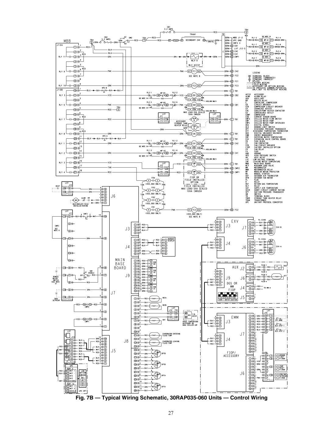
Fig. 7B — Typical Wiring Schematic, 30RAP035-060 Units — Control Wiring

27

Page 27
Image 27
Carrier 30RAP010-060 specifications A30-5284, Typical Wiring Schematic, 30RAP035-060 Units Control Wiring

30RAP010-060 specifications

The Carrier 30RAP010-060 is a series of rooftop air conditioning units designed for effective climate control in commercial applications. Engineered with advanced technologies, these units are known for their reliability, energy efficiency, and ease of installation, making them a suitable choice for a range of settings including offices, retail spaces, and industrial facilities.

One of the standout features of the 30RAP series is its robust construction. Designed to withstand various environmental conditions, these units come equipped with a weather-resistant cabinet and a corrosion-resistant finish. This durability ensures long-term performance and reduced maintenance costs.

Energy efficiency is a significant characteristic of the Carrier 30RAP series. These units utilize advanced technologies such as a high-efficiency compressor and variable speed fans. The inclusion of economizers also contributes to energy savings by allowing the system to take advantage of outdoor air when the conditions are favorable. With high SEER (Seasonal Energy Efficiency Ratio) ratings, the 30RAP units help businesses reduce operating costs while minimizing their environmental footprint.

The 30RAP series is equipped with smart control systems that provide enhanced operational efficiency and comfort. With features such as programmable thermostats and remote access capabilities, building managers can easily monitor and adjust the system to maintain optimal indoor climate conditions. Additionally, the units are compatible with building automation systems, allowing for seamless integration into a larger HVAC network.

The installation process of the Carrier 30RAP010-060 is streamlined thanks to a compact design and lightweight construction, which simplifies the transportation and placement on rooftops. Moreover, the unit's modular components facilitate easy access for maintenance and repairs, minimizing downtime and improving overall reliability.

In summary, the Carrier 30RAP010-060 series stands out for its combination of durability, energy efficiency, and advanced control technologies. It is an ideal solution for businesses seeking reliable climate control systems that balance performance with cost-effectiveness. Whether for new installations or replacements, these rooftop units provide the necessary flexibility and efficiency needed in today’s commercial environments. With strong backing from Carrier, a leader in HVAC technology, the 30RAP series ensures lasting comfort and operational efficiency.