Controls, Start-Up, Operation, Service, and Troubleshooting
Contents
Contents
Safety Considerations
Unit Sizes
General
Basic Controls Usage
Unit Nominal Capacity Tons
Accessory Navigator Display Module
Scrolling Marquee Display Menu Structure
Mode RUN Service Temperatures
SET Inputs Outputs Configuration Time Operating Alarms
Test
Run Status Mode and Sub-Mode Directory
Strt
SUB-MODE Keypad Display SUB-ITEM Comment Entry Expansion
Vers
Outs
Service Test Mode and Sub-Mode Directory
SUB-MODE Keypad Display Comment Entry Expansion Test
Cmpa
Pressure Mode and Sub-Mode Directory
Temperature Mode and Sub-Mode Directory
Set Points Mode and Sub-Mode Directory
Inputs Mode and Sub-Mode Directory
Outputs Mode and Sub-Mode Directory
Configuration Mode and Sub-Mode Directory
SUB-MODE Keypad Display Comment Entry Expansion EXV
OPT1
SUB-MODE Keypad Display Comment Entry Expansion Unit
SUB-MODE Keypad Display Comment
OPT2
XXX
XXX.X ΔF
Date
Time Clock Mode and Sub-Mode Directory
DST
Operating Mode and Sub-Mode Directory
Alarms Mode and Sub-Mode Directory
Mode Item Expansion Description
Operating Modes
Control Module Communication
Controls
Carrier Comfort Network CCN Interface
Status Inputs
CCN Communication Bus Wiring
Thermistor Designations
Output Relays
CCB
Almr
AUX
CHC
A30-4962
A30-4963
A30-4964
Typical Control Box for 30RAP035-060
Typical Wiring Schematic, 30RAP018-030 Units Power Wiring
Typical Wiring Schematic, 30RAP018-030 Units Control Wiring
A30-4966
Typical Wiring Schematic, 30RAP035-060 Units Power Wiring
5283
Typical Wiring Schematic, 30RAP035-060 Units Control Wiring
A30-5284
A30-4967
A30-4968
Page
CEPL130351
Deadband Multiplier
30RAP Unit Size Control Capacity Steps Capacity %
A30-4969
Operating Envelope for R-410A Compressor
A30-4970
Cooling Set Point Select
30RAP Unit Size FAN Stages
Control Occupancy Cooling SET Point Select Clsp Type State
Optional Factory-Installed Hydronic Pack
Control Methods and Cooling Set Points
CCN
→PM1E = YES
Configuring and Operating Dual Chiller Con
Dual Chiller Configuration Master Chiller Example
Rset
Number
Part
SUB-MODE Keypad Entry Display Item Expansion Comments
Dual Chiller Configuration Slave Chiller Example
Rset Slave Complete
To 20 mA Reset
Menu Configuration of 4 to 20 mA Cooling Set Point Control
Mode Keypad SUB Display
Configuring Outdoor Air and Space Temperature Reset
Configuring Return Temperature Reset
RED LED Entry Mode
Outdoor-Air Temperature Reset
To 20-mA Demand Limiting
PRE-START-UP
Configuring Demand Limit
Item Expansion Comment Entry Configuration
System Check
A30-4978
START-UP and Operation
30RAP Minimum Cooler Flow Maximum Cooler Flow Size
Operation Sequence
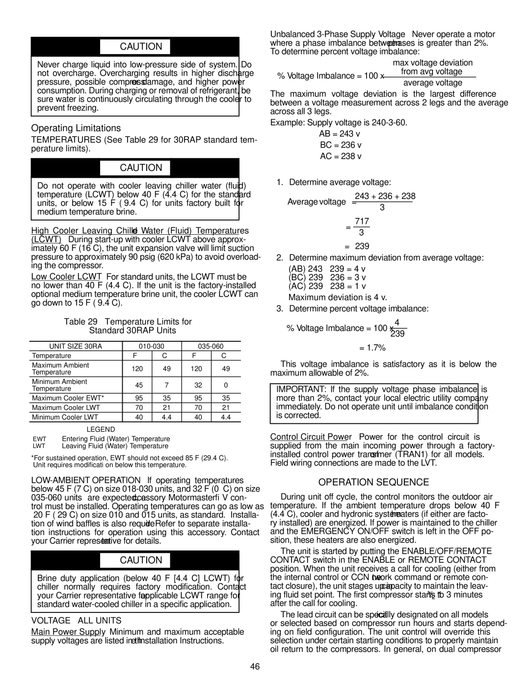
Temperature Limits for Standard 30RAP Units
Operating Limitations
Unit Size 30RA
EXV Steps
Service
Electronic Components
Unit Size 30RAP EXV Steps
A30-4971
Electronic Expansion Valve Details
Cooler
Compressor Replacement Refer to Fig
Unit Torque Specification
A30-4972
Oil Charge
Check Refrigerant Feed Components
A30-4974
A30-4973
LWT
Check Unit Safeties
Factory Settings, High-Pressure Switch Fixed
Unit Cutout CUT-IN
Thermistor Well
Temp Voltage Resistance Drop
100,260
143
86K Thermistor vs Resistance DTT
Drop
A30-4976
A30-4975
A30-499
Accsy
P50 Fault History Last 8 faults P51 Software version
TB1-TB2
Mode Nominal Voltage Control Input Start Jumper
A30-4977
TB13A-TB2
Fault Codes
Motormaster V Program Parameters for Operating Modes
Parameters Description Mode
PID
Replacement Modules
Maintenance
Replacement Replacement Part Module
Troubleshooting
Advanced Scroll Temperature Protection Label
30RAP Unit Cutout CUT-IN Size
Troubleshooting
Symptoms Cause Remedy
Alarm and Alert Codes
T051
T110
T153
T197
CSB
Alert GENERATED?
CCN
EMM
Compressor Stuck on Failure Alarms
Page
View
Appendix a Display Tables
SUB-MODE Display Item Description Comment
RUN
Strt
Appendix a Display Tables
Vers
Pressures Mode and Sub-Mode Directory
Head
SUB-MODE Display Item Description Range Comment
Cool
FRZ
GEN.O
SUB-MODE Display Item Description Comment
HP.A
HP.B
EXV.A
EXV.B
Rset
Bcst
DST
SUB-MODE Display Item Description Comment Time
Date
HOL.L
HD.19
HD.30
PER.1
SUB-MODE Display Item Description Comment SCH.N
SCH.L
PER.2
PER.7
PER.6
PER.8
Rcrn
Crnt
Hist
CCN Display Tables Circaan Circuit a Analog Parameters
Appendix B CCN Tables
CCN Display Tables Aunit General Unit Parameters
Description Value Units Point Name Forcible
Appendix B CCN Tables
CCN Display Tables Circban Circuit B Analog Parameters
Description Value Default Units Point Name
CCN Configuration Tables Unit Unit Configuration
CCN Configuration Tables OPTIONS1 Options 1 Configuration
CCN Display Tables Options Unit Parameters
CCN Configuration Tables OPTIONS2 Options 2 Configuration
CCN Configuration Tables Schedovr Timed Override Setup
CCN Configuration Tables Display Marquee Display Setup
CCN Configuration Tables Mmconf Motormaster Configuration
CCN Service Tables Service
Description Value Units Point Name
Description Value Point Name
CCN Maintenance Tables Alarms
Description Version Value
CCN Maintenance Tables PM-PUMP
CCN Maintenance Tables Runtest
CCN Maintenance Tables Dualchil
Appendix C Factory Settings for Pump and Manual Starters
Setting
Appendix D Optional Bacnet Communications Wiring
Optional BACnet Communications Wiring
Table B Baud Selection Table
Appendix D Optional Bacnet Communications Wiring
Table a SW3 Protocol Switch Settings For MS/TP
DS8 DS7 DS6 DS5 DS4 DS3
AWG
Table C MS/TP Wiring Recommendations
Specification Recommmendation
CL2P
Rmcorp
Wiring Specifications Recommended Vendors and Part Numbers
CMP
RUN LED Error LED Status
Table E LED Status Indicators
LED Status
Control Mode
Table G Network Points List
108
109
Weekly
Appendix E Maintenance Summary and LOG Sheets
30RAP Maintenance Interval Requirements
Quarterly
Appendix E Maintenance Summary and LOG Sheets
30RAP Weekly Maintenance Log
Unit Section Action Entry
30RAP Monthly Maintenance Log
PSI
30RAP Seasonal Shutdown Log
113
Copyright 2010 Carrier Corporation
II. Preliminary Equipment Check
START-UP Checklist for 30RAP Liquid Chiller
Remove and use for Job File Project Information
Design Information
III. Unit Start-Up
Start and Operate Machine. Complete the Following
Dual Chiller Control Only
Mode RUN Status
Record Software Versions
Submode Item Expansion Display Entry
Unit Configuration Settings
OPTIONS1 Options Configuration
OPT1
HP.A Head Pressure Cmp. Delta Configuration
OPTIONS2 Options Configuration
CCN CCN Network Configuration
HP.B Head Pressure Cmp. Delta Configuration
MM Motormaster Configuration Settings
EXV.A Circuit a EXV Configuration
EXV.B Circuit B EXV Configuration
EXV.B
Rset Reset Configuration Settings
Slct Setpoint and Ramp Load Configuration
Setpoint
SUB-MODE Keypad Display Comment
Entry Expansion