| | | Table 14 — Operating Modes |
| | | |
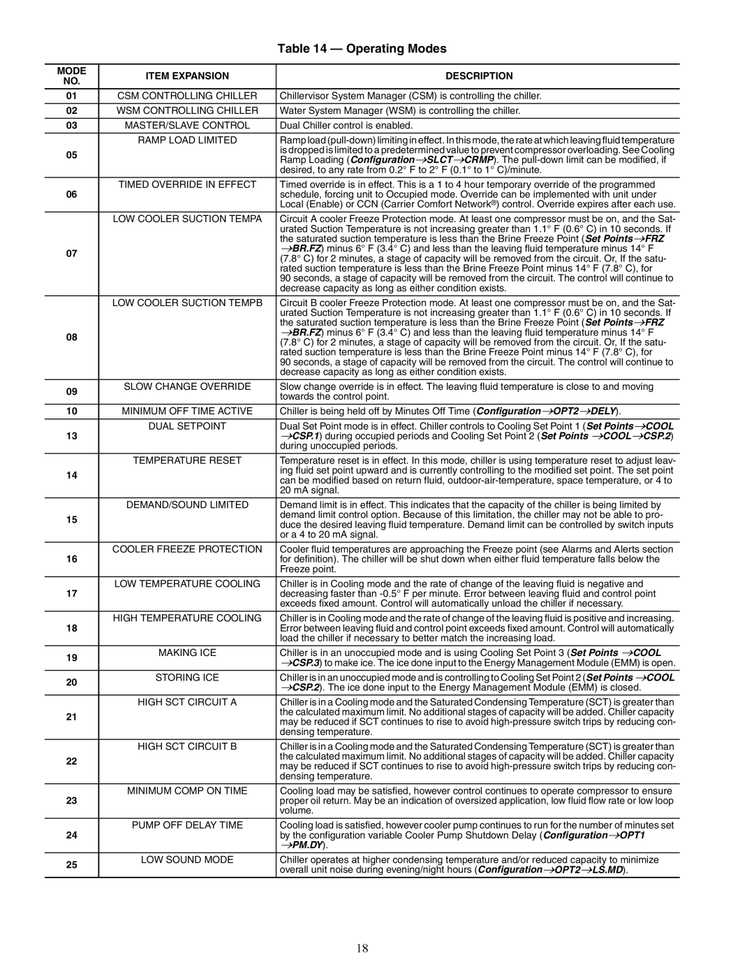
| MODE | ITEM EXPANSION | DESCRIPTION |
| NO. |
| | |
| 01 | CSM CONTROLLING CHILLER | Chillervisor System Manager (CSM) is controlling the chiller. |
| | | |
| 02 | WSM CONTROLLING CHILLER | Water System Manager (WSM) is controlling the chiller. |
| | | |
| 03 | MASTER/SLAVE CONTROL | Dual Chiller control is enabled. |
| | | |
| | RAMP LOAD LIMITED | Ramp load (pull-down) limiting in effect. In this mode, the rate at which leaving fluid temperature |
| 05 | | is dropped is limited to a predetermined value to prevent compressor overloading. See Cooling |
| | Ramp Loading (Configuration→SLCT→CRMP). The pull-down limit can be modified, if |
| | | desired, to any rate from 0.2° F to 2° F (0.1° to 1° C)/minute. |
| | | |
| 06 | TIMED OVERRIDE IN EFFECT | Timed override is in effect. This is a 1 to 4 hour temporary override of the programmed |
| | schedule, forcing unit to Occupied mode. Override can be implemented with unit under |
| | | Local (Enable) or CCN (Carrier Comfort Network®) control. Override expires after each use. |
| | LOW COOLER SUCTION TEMPA | Circuit A cooler Freeze Protection mode. At least one compressor must be on, and the Sat- |
| | | urated Suction Temperature is not increasing greater than 1.1° F (0.6° C) in 10 seconds. If |
| | | the saturated suction temperature is less than the Brine Freeze Point (Set Points→FRZ |
| 07 | | →BR.FZ) minus 6° F (3.4° C) and less than the leaving fluid temperature minus 14° F |
| | (7.8° C) for 2 minutes, a stage of capacity will be removed from the circuit. Or, If the satu- |
| | |
| | | rated suction temperature is less than the Brine Freeze Point minus 14° F (7.8° C), for |
| | | 90 seconds, a stage of capacity will be removed from the circuit. The control will continue to |
| | | decrease capacity as long as either condition exists. |
| | | |
| | LOW COOLER SUCTION TEMPB | Circuit B cooler Freeze Protection mode. At least one compressor must be on, and the Sat- |
| | | urated Suction Temperature is not increasing greater than 1.1° F (0.6° C) in 10 seconds. If |
| | | the saturated suction temperature is less than the Brine Freeze Point (Set Points→FRZ |
| 08 | | →BR.FZ) minus 6° F (3.4° C) and less than the leaving fluid temperature minus 14° F |
| | (7.8° C) for 2 minutes, a stage of capacity will be removed from the circuit. Or, If the satu- |
| | |
| | | rated suction temperature is less than the Brine Freeze Point minus 14° F (7.8° C), for |
| | | 90 seconds, a stage of capacity will be removed from the circuit. The control will continue to |
| | | decrease capacity as long as either condition exists. |
| 09 | SLOW CHANGE OVERRIDE | Slow change override is in effect. The leaving fluid temperature is close to and moving |
| | towards the control point. |
| | |
| | | |
| 10 | MINIMUM OFF TIME ACTIVE | Chiller is being held off by Minutes Off Time (Configuration→OPT2→DELY). |
| | | |
| | DUAL SETPOINT | Dual Set Point mode is in effect. Chiller controls to Cooling Set Point 1 (Set Points→COOL |
| 13 | | →CSP.1) during occupied periods and Cooling Set Point 2 (Set Points →COOL→CSP.2) |
| | | during unoccupied periods. |
| | TEMPERATURE RESET | Temperature reset is in effect. In this mode, chiller is using temperature reset to adjust leav- |
| 14 | | ing fluid set point upward and is currently controlling to the modified set point. The set point |
| | can be modified based on return fluid, outdoor-air-temperature, space temperature, or 4 to |
| | |
| | | 20 mA signal. |
| | | |
| | DEMAND/SOUND LIMITED | Demand limit is in effect. This indicates that the capacity of the chiller is being limited by |
| 15 | | demand limit control option. Because of this limitation, the chiller may not be able to pro- |
| | duce the desired leaving fluid temperature. Demand limit can be controlled by switch inputs |
| | |
| | | or a 4 to 20 mA signal. |
| | | |
| 16 | COOLER FREEZE PROTECTION | Cooler fluid temperatures are approaching the Freeze point (see Alarms and Alerts section |
| | for definition). The chiller will be shut down when either fluid temperature falls below the |
| | | Freeze point. |
| | | |
| 17 | LOW TEMPERATURE COOLING | Chiller is in Cooling mode and the rate of change of the leaving fluid is negative and |
| | decreasing faster than -0.5° F per minute. Error between leaving fluid and control point |
| | | exceeds fixed amount. Control will automatically unload the chiller if necessary. |
| | | |
| 18 | HIGH TEMPERATURE COOLING | Chiller is in Cooling mode and the rate of change of the leaving fluid is positive and increasing. |
| | Error between leaving fluid and control point exceeds fixed amount. Control will automatically |
| | | load the chiller if necessary to better match the increasing load. |
| 19 | MAKING ICE | Chiller is in an unoccupied mode and is using Cooling Set Point 3 (Set Points →COOL |
| | →CSP.3) to make ice. The ice done input to the Energy Management Module (EMM) is open. |
| | | |
| 20 | STORING ICE | Chiller is in an unoccupied mode and is controlling to Cooling Set Point 2 (Set Points →COOL |
| | →CSP.2). The ice done input to the Energy Management Module (EMM) is closed. |
| | | |
| | HIGH SCT CIRCUIT A | Chiller is in a Cooling mode and the Saturated Condensing Temperature (SCT) is greater than |
| 21 | | the calculated maximum limit. No additional stages of capacity will be added. Chiller capacity |
| | may be reduced if SCT continues to rise to avoid high-pressure switch trips by reducing con- |
| | |
| | | densing temperature. |
| | | |
| | HIGH SCT CIRCUIT B | Chiller is in a Cooling mode and the Saturated Condensing Temperature (SCT) is greater than |
| 22 | | the calculated maximum limit. No additional stages of capacity will be added. Chiller capacity |
| | may be reduced if SCT continues to rise to avoid high-pressure switch trips by reducing con- |
| | |
| | | densing temperature. |
| | | |
| 23 | MINIMUM COMP ON TIME | Cooling load may be satisfied, however control continues to operate compressor to ensure |
| | proper oil return. May be an indication of oversized application, low fluid flow rate or low loop |
| | | volume. |
| | | |
| | PUMP OFF DELAY TIME | Cooling load is satisfied, however cooler pump continues to run for the number of minutes set |
| 24 | | by the configuration variable Cooler Pump Shutdown Delay (Configuration→OPT1 |
| | | →PM.DY). |
| | | |
| 25 | LOW SOUND MODE | Chiller operates at higher condensing temperature and/or reduced capacity to minimize |
| | overall unit noise during evening/night hours (Configuration→OPT2→LS.MD). |
| | | |