1-51
CiscoASR 9000 Series Aggregation Services Router Hardware Installation Guide
Chapter1 Preparing for Installation
Site Requirement Guidelines
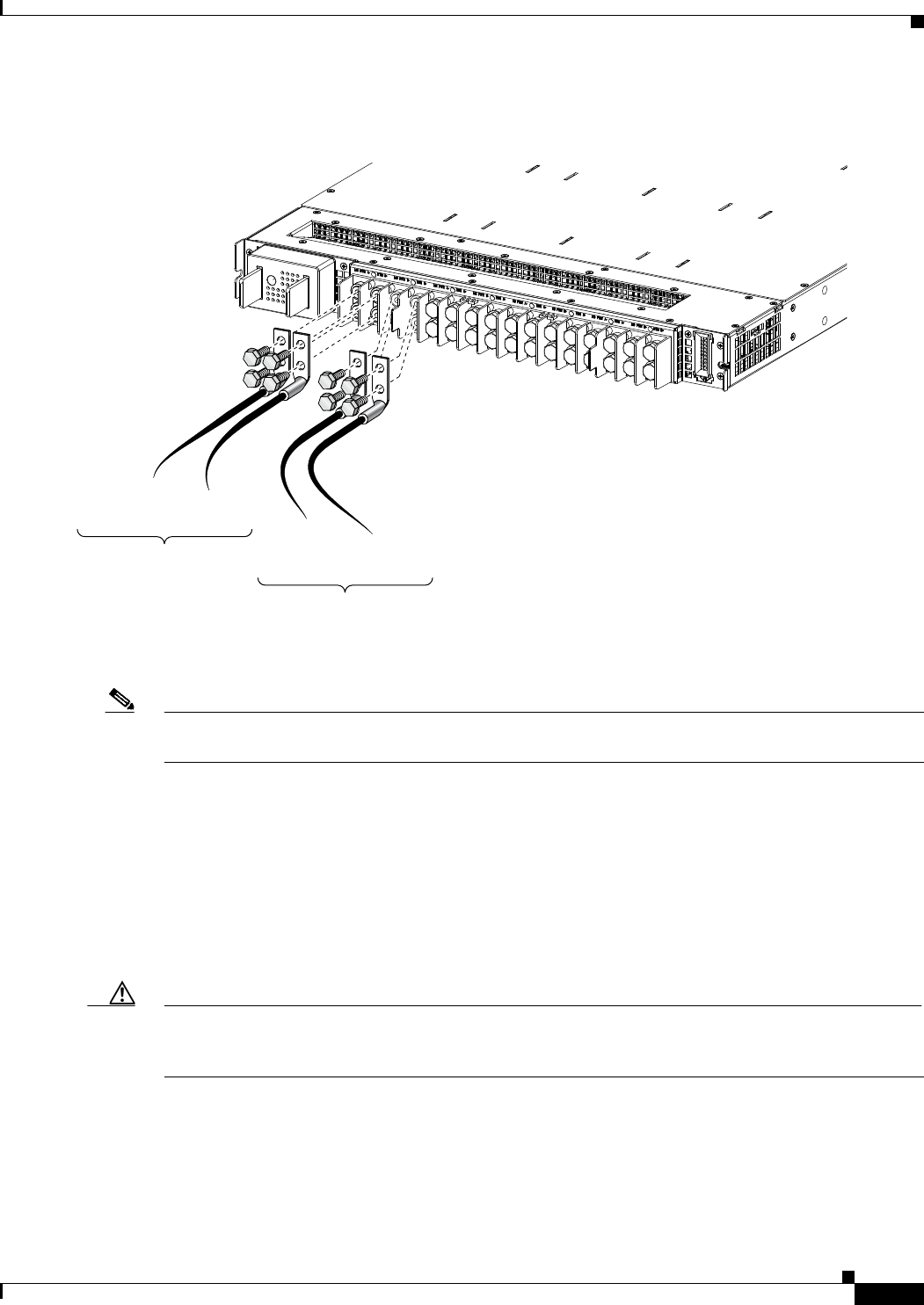
Figure1-56 Typical Source DC Power Cabling Scheme for a Single DC Power Module—Version 3 Power System
Note A separate ground connection is not required for the version 2 or version 3 power systems. For more
information see the NEBS Supplemental Unit Bonding and Grounding Guidelines, page1-52.
The color coding of source DC power cable leads depends on the color coding of the site DC power
source. Because there is no color code standard for source DC wiring, be sure that power source cables
are connected to the power modules using the proper positive(+) and negative (–) polarity:
•In some cases, the source DC cable leads might have a positive(+) or a negative (–) label. This is a
relatively safe indication of the polarity, but you must verify the polarity by measuring the voltage
between the DC cable leads. Be sure that the positive (+) and negative (–) cable leads match the
positive (+) and negative (–) labels on the power module when making the measurement.
•Green (or green and yellow) cable typically indicates that it is a ground cable.
Caution DC power modules contain reverse voltage protection circuitry to prevent damage to the power module
if it detects a reverse polarity condition. No damage should occur from reverse polarity, but you should
correct a reverse polarity condition immediately.
For a list of the nominal and acceptable value ranges for source DC power, see “Appendix A.”
364234
PWR A–
–48/60V PWR RTN A+
–48/60V RTN
Feed A, Slot M3
PWR B–
–48/60V PWR RTN B+
–48/60V RTN
Feed B, Slot M3