Configuration Options
The following sections describe the initial
Initial Power-On Sequence
When connected and first powered on, the Cisco uBR900 series cable access router performs the following boot procedures:
•Boots the Read Only Memory (ROM) from the ROMMON partition of its flash memory.
•Performs a
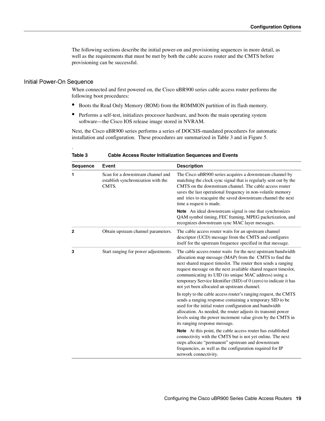
Next, the Cisco uBR900 series performs a series of
.
Table 3 | Cable Access Router Initialization Sequences and Events | |
|
|
|
Sequence | Event | Description |
|
|
|
1 | Scan for a downstream channel and | The Cisco uBR900 series acquires a downstream channel by |
| establish synchronization with the | matching the clock sync signal that is regularly sent out by the |
| CMTS. | CMTS on the downstream channel. The cable access router |
|
| saves the last operational frequency in |
|
| and tries to reacquire the saved downstream channel the next |
|
| time a request is made. |
Note An ideal downstream signal is one that synchronizes QAM symbol timing, FEC framing, MPEG packetization, and recognizes downstream sync MAC layer messages.
2Obtain upsteam channel parameters. The cable access router waits for an upstream channel descriptor (UCD) message from the CMTS and configures itself for the upstream frequence specified in that message.
3Start ranging for power adjustments. The cable access router waits for the next upstream bandwidth allocation map message (MAP) from the CMTS to find the next shared request timeslot. The router then sends a ranging request message on the next available shared request timeslot, communicating its UID (its unique MAC address) using a temporary Service Identifier (SID) of 0 (zero) to indicate it has not yet been allocated an upstream channel.
In reply to the cable access router’s ranging request, the CMTS sends a ranging response containing a temporary SID to be used for the initial router configuration and bandwidth allocation. As needed, the router adjusts its transmit power levels using the power increment value given by the CMTS in its ranging response message.
Note At this point, the cable access router has established connectivity with the CMTS but is not yet online. The next steps allocate “permanent” upstream and downstream frequencies, as well as the configuration required for IP network connectivity.
Configuring the Cisco uBR900 Series Cable Access Routers 19