Figure 2-6. PowerConnect 2824 Back Panel
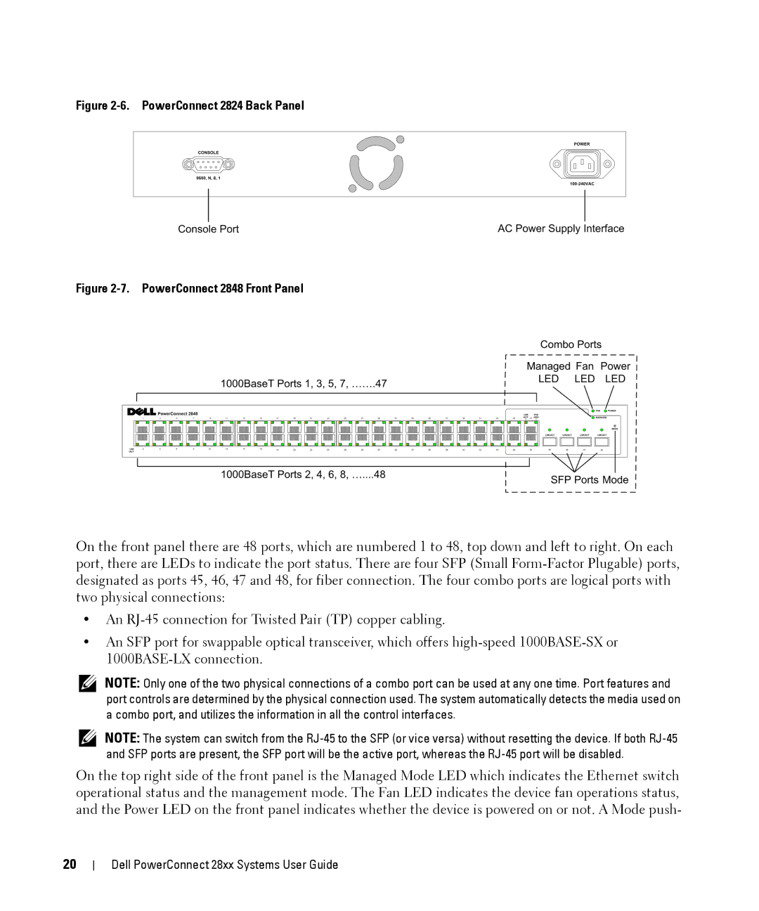
Figure 2-7. PowerConnect 2848 Front Panel
On the front panel there are 48 ports, which are numbered 1 to 48, top down and left to right. On each port, there are LEDs to indicate the port status. There are four SFP (Small
•An
•An SFP port for swappable optical transceiver, which offers
NOTE: Only one of the two physical connections of a combo port can be used at any one time. Port features and port controls are determined by the physical connection used. The system automatically detects the media used on a combo port, and utilizes the information in all the control interfaces.
NOTE: The system can switch from the
On the top right side of the front panel is the Managed Mode LED which indicates the Ethernet switch operational status and the management mode. The Fan LED indicates the device fan operations status, and the Power LED on the front panel indicates whether the device is powered on or not. A Mode push-
20
Dell PowerConnect 28xx Systems User Guide