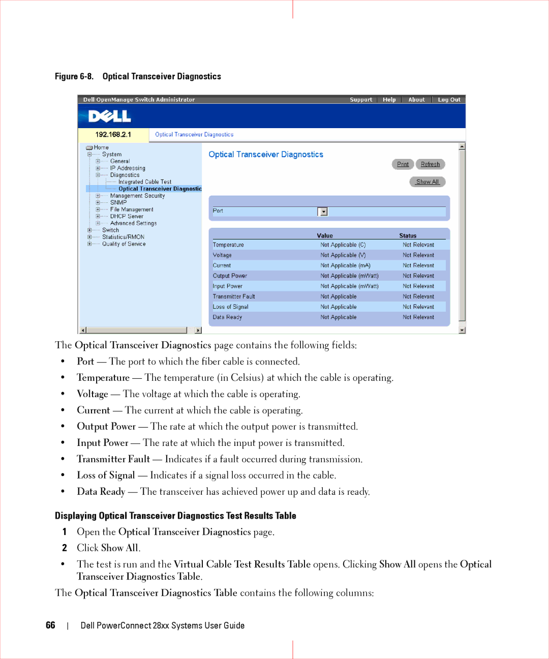
Figure 6-8. Optical Transceiver Diagnostics
The Optical Transceiver Diagnostics page contains the following fields:
•Port — The port to which the fiber cable is connected.
•Temperature — The temperature (in Celsius) at which the cable is operating.
•Voltage — The voltage at which the cable is operating.
•Current — The current at which the cable is operating.
•Output Power — The rate at which the output power is transmitted.
•Input Power — The rate at which the input power is transmitted.
•Transmitter Fault — Indicates if a fault occurred during transmission.
•Loss of Signal — Indicates if a signal loss occurred in the cable.
•Data Ready — The transceiver has achieved power up and data is ready.
Displaying Optical Transceiver Diagnostics Test Results Table
1Open the Optical Transceiver Diagnostics page.
2Click Show All.
•The test is run and the Virtual Cable Test Results Table opens. Clicking Show All opens the Optical Transceiver Diagnostics Table.
The Optical Transceiver Diagnostics Table contains the following columns:
66
Dell PowerConnect 28xx Systems User Guide