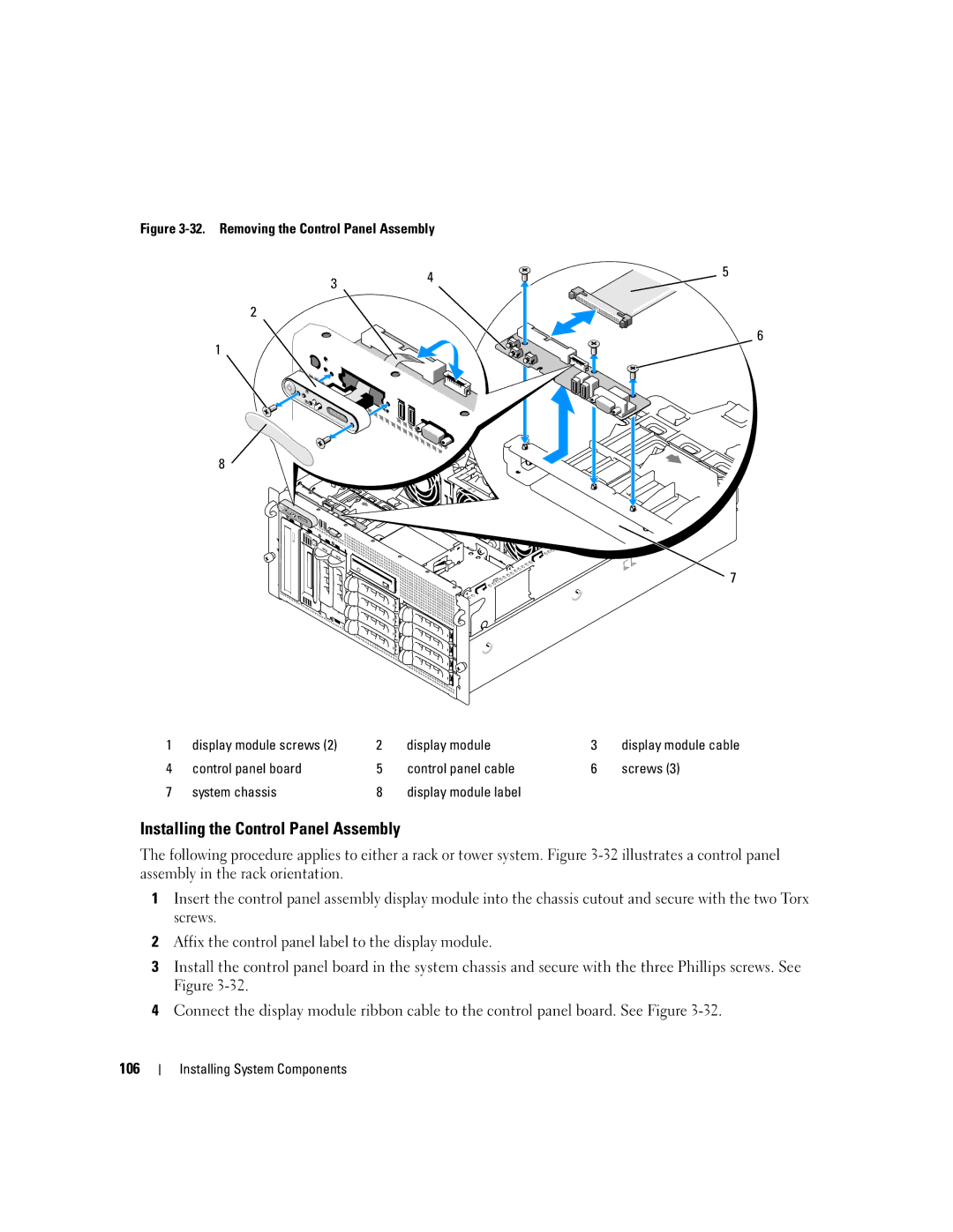
Figure 3-32. Removing the Control Panel Assembly
3 | 4 | 5 |
| ||
|
|
2
![]()
![]()
![]()
![]() 6 1
6 1![]()
![]()
![]()
![]()
![]()
![]()
![]()
![]()
![]()
![]()
![]()
![]()
8
![]() 7
7
1 | display module screws (2) | 2 | display module | 3 | display module cable |
4 | control panel board | 5 | control panel cable | 6 | screws (3) |
7 | system chassis | 8 | display module label |
|
|
Installing the Control Panel Assembly
The following procedure applies to either a rack or tower system. Figure
1Insert the control panel assembly display module into the chassis cutout and secure with the two Torx screws.
2Affix the control panel label to the display module.
3Install the control panel board in the system chassis and secure with the three Phillips screws. See Figure
4Connect the display module ribbon cable to the control panel board. See Figure
106