W . d e l l . c o m s u p p o r t . d e l l . c o m
Dell PowerEdge 2900 Systems
December
Contents
Baseboard Management Controller Configuration
Installing System Components
General Memory Module Installation Guidelines
Removing or Installing the Cooling Shroud Fan
Installing the Diskette Drive Into the Drive Carrier
109
Cabling the SAS Controller Non-RAID
101
105
116
Troubleshooting System Cooling Problems 123
Troubleshooting an External Scsi Tape Drive 128
Using Server Administrator Diagnostics 135
141
Returning Items for Warranty Repair or Credit 149
137
139
About Your System
About Your System
Other Information You May Need
System Orientation
Accessing System Features During Startup
Front-Panel Features and Indicators
Tape backup unit
LCD lights amber when the system needs
Whether the system has been powered on
USB connectors
Amber About Your System
Hard-Drive Indicator Codes
About Your System
Connector Power supply
Back-Panel Features and Indicators
Connecting External Devices
System status indicator Power supply 2 optional
Green indicates that the power supply is operational
Power Indicator Codes
Redundant Power Supply Indicators
Indicator Function
LCD Status Messages
NIC Indicator Codes
E1210 Cmos Batt
E1000 FAILSAFE, Call
Support E1114 Temp Ambient
E1116 Temp Memory
E141C CPU Mismatch
E1410
E1414 CPU # Thermtrip
E1418 CPU # Presence
E1618 PS # Predictive
E1422 CPU Machine Chk
E1610 PS # Missing
E1614 PS # Status
E1714 Unknown Err
E1810 HDD ## Fault
E1712
PCI Serr Slot #
E1A15 SAS Cable B
E2011 Mem Config Err
E2013 Shadow Bios Fail
E1A14 SAS Cable a
E201F Drac Config
E2017 Timer Fail
E2018 Prog Timer
E2019 Parity Error
Fully Buffered Dimm FBD
Removing LCD Status Messages
Solving Problems Described by LCD Status Messages
System Messages
Remote Configuration
Disabled! Memory
Configuration does not
Attempting to update
Dual-rank Dimm paired with
Been disabled by Bios
Diskette subsystem reset
Error Remote Access
Manufacturing mode
FBD training error
Disabled Branch
Configuration, Resource
Northbound merge error
No boot device available
No boot sector on hard drive
No timer tick Interrupt
Read fault Requested sector not found
PCI Bios failed to install
Plug & Play Configuration
Error
Following Dimm pair is
Please run Setup program
Timer chip counter
Update loaded for
Alert Messages
Diagnostics Messages
About Your System
Using the System Setup Program
Entering the System Setup Program
Responding to Error Messages
Main Screen
System Setup Options
Using the System Setup Program
Logical Processor option. See Table
System memory test option, and redundant memory status
CPU Information
From external devices
System Setup Program Options Description Sata Port
Boot Sequence
Network
CPU Information Screens
Integrated Devices Screen
System Security Screen
Serial Communication Screen
Exit Screen
Using the System Password
System and Setup Password Features
Using the System Setup Program
Deleting or Changing an Existing System Password
Using the Setup Password
See Disabling a Forgotten Password on
Disabling a Forgotten Password
Baseboard Management Controller Configuration
BMC Setup Module Options
Entering the BMC Setup Module
Using the System Setup Program
Recommended Tools
Installing System Components
Removing the Bezel
Opening and Closing the System
Bezel latch Installing System Components
Installing and Removing the Optional Bezel Tower Keylock
Bay panel Bezel inside view Tab slot
Installing the Peripheral Bay Panel Tower Only
Removing the Peripheral Bay Panel Tower Only
Peripheral bay panel
Closing the System
Installing the Bezel
Opening the System
Cover latch
Hot-Plug Hard Drives
Hard-Drive Bay Numbers Rack 1x2 flex bay hard drives
Before You Begin
Removing a Hot-Plug Hard Drive
Installing a Drive Blank
Installing a Hot-Plug Hard Drive
Removing a Drive Blank
Installing a Hot-Plug Hard Drive
Removing a Hard Drive From a Hard-Drive Carrier
Installing a SAS Hard Drive Into a SATAu Drive Carrier
Replacing a Hard-Drive Carrier
Installing a Sata Hard Drive Into a Sata Drive Carrier
Sata hard drive
Sata hard-drive Hole labels Installing System Components
Removing a Power Supply
Power Supplies
Power supply Handle Tab Power supply blank Screw
Installing a Power Supply
Fans
Removing the Power Supply Blank
Installing the Power Supply Blank
Processor fan FAN2 Processor fan FAN3
Removing and Installing a Fan
Fan connector on system board
Removing or Installing the Cooling Shroud Fan
Fan bracket latch Installing System Components
Expansion Cards
Installing an Expansion Card
Card-edge guide Expansion card
15. Installing and Removing Expansion Cards
Removing an Expansion Card
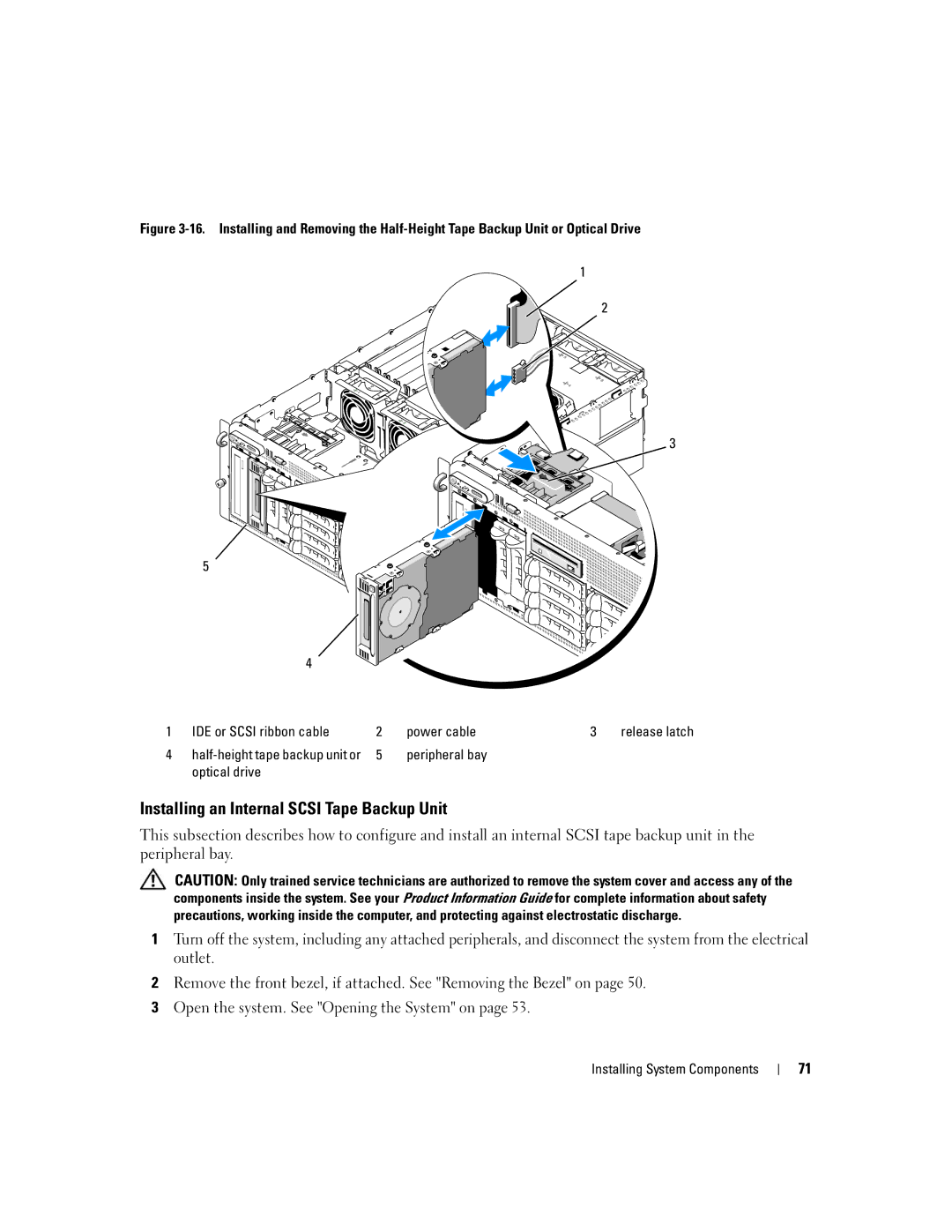
Internal Scsi Tape Backup Unit
Removing an Internal Scsi Tape Backup Unit
Peripheral bay Optical drive
Installing an Internal Scsi Tape Backup Unit
Installing System Components
Removing an Optical Drive
Installing an Optical Drive
Optical Drive
Removing the Diskette Drive
Diskette Drive
Diskette drive power cable
Installing the Diskette Drive
Installing the Diskette Drive Into the Drive Carrier
Replacing the System Battery
System Battery
Negative side of connector
Removing the Cooling Shroud
Cooling Shroud
Cooling shroud latch right
Replacing the Center Fan Bracket
Installing the Cooling Shroud
Fan Brackets
Removing the Center Fan Bracket
Replacing the Back Fan Bracket
Memory
Removing the Back Fan Bracket
21. Dimm Sockets Installing System Components
Memory Sparing Support
General Memory Module Installation Guidelines
Non-Optimal Memory Configurations
Memory Mirroring Support
Installing Memory Modules
Memory module socket ejectors
Removing Memory Modules
Installing a RAC Card
RAC card RAC connector Expansion-bay bracket
23. Installing a RAC Card Notch in card edge Back standoff
Replacing a Processor
Activating the Integrated NIC TOE
Microprocessor
24. Installing and Removing the Heat Sink Heat sink
ZIF socket Processor
Installing System Components
Removing the 1x8 SAS Backplane Board
Installing the 1x8 SAS Backplane Board
1x8 SAS Backplane Board
Removing the 1x2 Flex Bay Drive Bracket
Optional 1x2 Flex Bay Drive Bracket
26. Installing and Removing the Flex Bay Drive Bracket
Installing the 1x2 Flex Bay Drive Bracket
SAS Controller Daughter Card
Replacing the SAS RAID Controller Daughter Card Battery
Card
RAID battery cable
Cable RAID battery Connector release tab Battery bay
Removing the SAS Controller Daughter Card
Only out to 1x8 backplane Sasb connector or Sasbin connector
Cabling the SAS Controller Non-RAID
Installing the SAS Controller Daughter Card
Cabling the SAS Backplane Boards
Cable Requirements
100
Sasa connector
101
Cabling the SAS RAID Controller
102
SAS1 connector
Card Dimm not shown 1x8 SAS backplane Sasb connector
103
104
105
Configuring the Boot Drive
Control Panel Assembly Service-Only Procedure
Removing the Control Panel Assembly
Display module
Installing the Control Panel Assembly
107
System Board Service-Only Procedure
Removing the System Board
Installing System Components
109
Installing the System Board
110
Power Distribution Board Service-Only Procedure
Removing the Power Distribution Board
111
Installing the Power Distribution Board
113
114
115
Safety First-For You and Your System
Start-Up Routine
116
Troubleshooting IRQ Assignment Conflicts
Troubleshooting External Connections
Checking the Equipment
Problem
Troubleshooting the Video Subsystem
Troubleshooting the Keyboard
Monitor is not working properly Video memory is faulty
Troubleshooting the Mouse
Troubleshooting Basic I/O Functions
119
Troubleshooting a Serial I/O Device
Troubleshooting a USB Device
Liquid spilled on the system Excessive humidity
Troubleshooting a NIC
Troubleshooting a Wet System
NIC cannot communicate with network
121
Troubleshooting a Damaged System
System was dropped or damaged
Troubleshooting Power Supplies
Troubleshooting the System Battery
123
Troubleshooting System Cooling Problems
Troubleshooting a Fan
Troubleshooting System Memory
125
Error message indicates a diskette drive problem
Troubleshooting a Diskette Drive
127
Troubleshooting an Optical Drive
Troubleshooting an External Scsi Tape Drive
129
Troubleshooting a Hard Drive
Troubleshooting a SAS or SAS RAID Controller Daughter Card
131
Troubleshooting Expansion Cards
Action
133
Troubleshooting the Microprocessors
Troubleshooting Your System
135
Using Server Administrator Diagnostics
System Diagnostics Features
When to Use the System Diagnostics
Selecting Devices for Testing
Running the System Diagnostics
System Diagnostics Testing Options
Using the Custom Test Options
137
Selecting Diagnostics Options
Viewing Information and Results
138
139
Jumpers and Connectors
System Board Jumpers
140
Boot
Configuration settings in Nvram are cleared at next
System boot
141
System Board Connectors
SAS Backplane Connectors
143
X2 SAS Backplane Connectors Power connector Sasbin connector
145
146
Getting Help
Online Services
Technical Assistance
147
Electronic Quote Service
AutoTech Service
Automated Order-Status Service
Technical Support Service
149
150
Before You Call