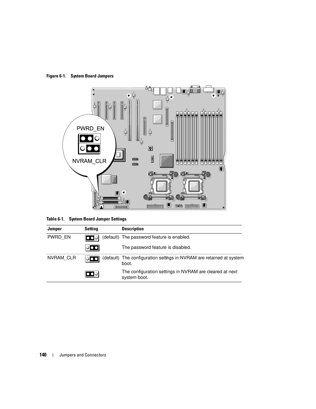
Dell PowerEdge 2900 Systems
Hardware Owner’s Manual
Notes, Notices, and Cautions
December
1 About Your System
Contents
2 Using the System Setup Program
3 Installing System Components
Installing a SATA Hard Drive and Interposer Card Into a SATAu
Removing the Power Supply Blank
4 Troubleshooting Your System
Replacing the SAS RAID Controller Daughter Card Battery
5 Running the System Diagnostics
Troubleshooting a SAS or SAS RAID Controller Daughter Card
Jumpers and Connectors
Getting Help
About Your System
system control panel rack
System Orientation
Other Information You May Need
Accessing System Features During Startup
Front-Panel Features and Indicators
The identification buttons on the front and back panels
green drive-activity indicator
Hard-Drive Indicator Codes
drive-status indicator green
Blinks green three seconds, amber three seconds, and off six seconds
Back-Panel Features and Indicators
Connecting External Devices
Power Indicator Codes
Power supply status
The NIC is connected to a valid link partner on the network
NIC Indicator Codes
LCD Status Messages
SYSTEM NAME
E1000
Controller User’s Guide for
E1410
Baseboard Management
E1422
Table 1-6. LCD Status Messages continued
E1A14
E2017
Fully Buffered DIMM FBD
Removing LCD Status Messages
Solving Problems Described by LCD Status Messages
System Messages
Alert! Redundant memory
Dual-rank DIMM paired with
Table 1-7. System Messages continued
value expecting value
Table 1-7. System Messages continued
PCI BIOS failed to install
Table 1-7. System Messages continued
Diagnostics Messages
Warning Messages
Alert Messages
memory configuration is
About Your System
Responding to Error Messages
Using the System Setup Program
Entering the System Setup Program
Main Screen
System Setup Options
Using the System Setup Program
Page
Auto default
On default
Report Keyboard Errors
Report default
CPU Information Screens
Integrated Devices Screen
All Ports On default
Enabled with PXE
Enabled without PXE
Serial Communication Screen
System Security Screen
VT 100/VT 220 default
Options are On with Console Redirection via COM2, and Off
Save Changes and Exit Discard Changes and Exit Return to Setup
Exit Screen
System and Setup Password Features
Using the System Password
4 Press Enter
Using the Setup Password
Disabling a Forgotten Password
Baseboard Management Controller Configuration
Entering the BMC Setup Module
BMC Setup Module Options
Using the System Setup Program
Installing System Components
Recommended Tools
Opening and Closing the System
Removing the Bezel
Removing the Tower Bezel
Installing the Peripheral Bay Panel Tower Only
Removing the Peripheral Bay Panel Tower Only
Closing the System
Installing the Bezel
Opening the System
Hot-Plug Hard Drives
chassis hooks
Before You Begin
Installing a Drive Blank
Installing a Hot-Plug Hard Drive
Removing a Drive Blank
Removing a Hot-Plug Hard Drive
3 Install the hot-plug hard drive
a Open the handle on the hard-drive carrier
c Close the handle to lock the drive in place
4 Replace the front bezel, if it was removed in step
Removing a Hard Drive From a Hard-Drive Carrier
Installing a SAS Hard Drive Into a SATAu Drive Carrier
Replacing a Hard-Drive Carrier
Installing a SATA Hard Drive Into a SATA Drive Carrier
SATA hard drive
4 Attach the interposer card to the rear of the SATA hard drive
Power Supplies
Removing a Power Supply
locking tab
Installing a Power Supply
Figure 3-10. Installing and Removing a Power Supply
Fans
Removing the Power Supply Blank
Installing the Power Supply Blank
Removing and Installing a Fan
2 Open the system. See Opening the System on page
Removing or Installing the Cooling Shroud Fan
1 Remove the front bezel, if attached. See Removing the Bezel on page
5 Replace the fan
Installing an Expansion Card
Expansion Cards
4 Remove the filler bracket on the slot you will be using
Removing an Expansion Card
Internal SCSI Tape Backup Unit
Removing an Internal SCSI Tape Backup Unit
Installing an Internal SCSI Tape Backup Unit
6 Remove the filler plates from the peripheral bay
Removing an Optical Drive
Installing an Optical Drive
Optical Drive
Diskette Drive
Removing the Diskette Drive
Figure 3-17. Installing and Removing the Diskette Drive
Installing System Components
diskette drive power cable
diskette drive
Installing the Diskette Drive Into the Drive Carrier
Installing the Diskette Drive
System Battery
Replacing the System Battery
5 Remove the system battery
Cooling Shroud
Removing the Cooling Shroud
Installing System Components
cooling shroud latch left
cooling shroud
back fan bracket
Installing the Cooling Shroud
Fan Brackets
Removing the Center Fan Bracket
Replacing the Center Fan Bracket
Replacing the Back Fan Bracket
Memory
Removing the Back Fan Bracket
Installing System Components
Each channel consists of three DIMM sockets
Channel 0 contains DIMM1, DIMM5, and DIMM9
Channel 1 contains DIMM 2, DIMM6, and DIMM10
Memory Sparing Support
General Memory Module Installation Guidelines
Non-Optimal Memory Configurations
Installing Memory Modules
Memory Mirroring Support
socket
Installing a RAC Card
Removing Memory Modules
6 Attach the card to the expansion-bay bracket
Replacing a Processor
Activating the Integrated NIC TOE
Microprocessor
heat-sink retention lever
retention lever latch
7 Wait 30 seconds for the heat sink to loosen from the processor
16 Install the processor in the socket
Removing the 1x8 SAS Backplane Board
Installing the 1x8 SAS Backplane Board
1x8 SAS Backplane Board
Optional 1x2 Flex Bay Drive Bracket
Removing the 1x2 Flex Bay Drive Bracket
Installing the 1x2 Flex Bay Drive Bracket
SAS connector SASBOUT
Replacing the SAS RAID Controller Daughter Card Battery
SAS Controller Daughter Card
SAS RAID controller daughter
Removing the SAS Controller Daughter Card
routing hole for RAID battery
SAS connector 1 SAS RAID
backplane SASA connector
RAID battery cable SAS RAID
SAS controller daughter card
Installing the SAS Controller Daughter Card
Cabling the SAS Backplane Boards
Cable Requirements
Cabling the SAS Controller Non-RAID
SAS connector
SASA connector
Installing System Components
Figure 3-29. Cabling the SAS Controller Non-RAID
Cabling the SAS RAID Controller
SAS1 connector
SASB connector
Installing System Components
SASA connector
1x8 Plus 1x2 Drive Configuration
SAS0 connector connect to
Removing the Control Panel Assembly
Configuring the Boot Drive
Control Panel Assembly Service-Only Procedure
display module cable
Installing the Control Panel Assembly
display module screws
System Board Service-Only Procedure
Removing the System Board
13 Remove the expansion-bay bracket
Installing the System Board
Power Distribution Board Service-Only Procedure
Removing the Power Distribution Board
2 Detach all cables from the rear of the system
Installing the Power Distribution Board
9 Close the system. See Closing the System on page
10 Reinsert the power supplies. See Installing a Power Supply on page
Installing System Components
Start-Up Routine
Troubleshooting Your System
Safety First-For You and Your System
Checking the Equipment
Troubleshooting IRQ Assignment Conflicts
Troubleshooting External Connections
Troubleshooting the Video Subsystem
Troubleshooting the Keyboard
Troubleshooting Basic I/O Functions
Troubleshooting the Mouse
Troubleshooting a Serial I/O Device
Troubleshooting a USB Device
Troubleshooting a NIC
Troubleshooting a Wet System
Troubleshooting a Damaged System
Troubleshooting the System Battery
Troubleshooting Power Supplies
Troubleshooting System Cooling Problems
Troubleshooting a Fan
Troubleshooting System Memory
4 Remove the bezel. See Removing the Bezel on page
Troubleshooting a Diskette Drive
Troubleshooting an Optical Drive
Troubleshooting an External SCSI Tape Drive
Troubleshooting a Hard Drive
Troubleshooting a SAS or SAS RAID Controller Daughter Card
Troubleshooting Expansion Cards
2 Open or remove the bezel. See Removing the Bezel on page
Troubleshooting the Microprocessors
17 Close the system. See Closing the System on page
18 Run the appropriate online diagnostic test
Troubleshooting Your System
Running the System Diagnostics
Using Server Administrator Diagnostics
System Diagnostics Features
When to Use the System Diagnostics
Running the System Diagnostics
System Diagnostics Testing Options
Using the Custom Test Options
Selecting Devices for Testing
Selecting Diagnostics Options
Viewing Information and Results
Running the System Diagnostics
Jumpers and Connectors
System Board Jumpers
The configuration settings in NVRAM are retained at system
System Board Connectors
SAS Backplane Connectors
optical drive/tape backup unit
Disabling a Forgotten Password
SASBOUT connector
10 Close the system. See Closing the System on page
Jumpers and Connectors
Technical Assistance
Online Services
Getting Help
Technical Support Service
AutoTech Service
Automated Order-Status Service
Problems With Your Order
Returning Items for Warranty Repair or Credit
Dell Enterprise Training and Certification
Product Information
Before You Call
Page
support.dell.com support
Contacting Dell
To contact Dell electronically, you can access the following websites
Country City
Country City
Country City
Country City
Country City
Country City
Country City
Country City
Country City
Country City
800 300 410 or 800 300 411 or
Country City
Country City
Country City
Country City
Printers, and Projectors for Relationship
or toll-free
Glossary
DIN - Deutsche Industrie Norm
expansion-card connector - A connector on the system board or riser board for plugging in an expansion card
local bus - On a system with local-bus expansion capability, certain peripheral devices such as the video adapter circuitry can be designed to run much faster than they would with a traditional expansion bus. See also bus
peripheral - An internal or external device, such as a diskette drive or keyboard, connected to a system
system diskette - See bootable diskette system memory - See RAM
UPS - Uninterruptible power supply. A battery-powered unit that automatically supplies power to your system in the event of an electrical failure
Glossary
Index
Page
Page
Page
troubleshooting continued NIC power supplies
USB device troubleshooting
video troubleshooting
warning messages warranty wet system troubleshooting
Index