Chapter 9: Sample Configurations
___________________________________________________________________
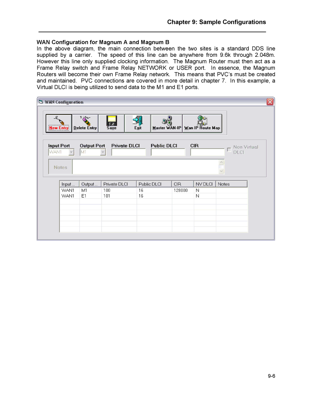
WAN Configuration for Magnum A and Magnum B
In the above diagram, the main connection between the two sites is a standard DDS line supplied by a carrier. The speed of this line can be anywhere from 9.6k through 2.048m. However this line only supplied clocking information. The Magnum Router must then act as a Frame Relay switch and Frame Relay NETWORK or USER port. In essence, the Magnum Routers will become their own Frame Relay network. This means that PVC’s must be created and maintained. PVC connections are covered in more detail in chapter 7. In this example, a Virtual DLCI is being utilized to send data to the M1 and E1 ports.