Chapter 9: Sample Configurations
___________________________________________________________________
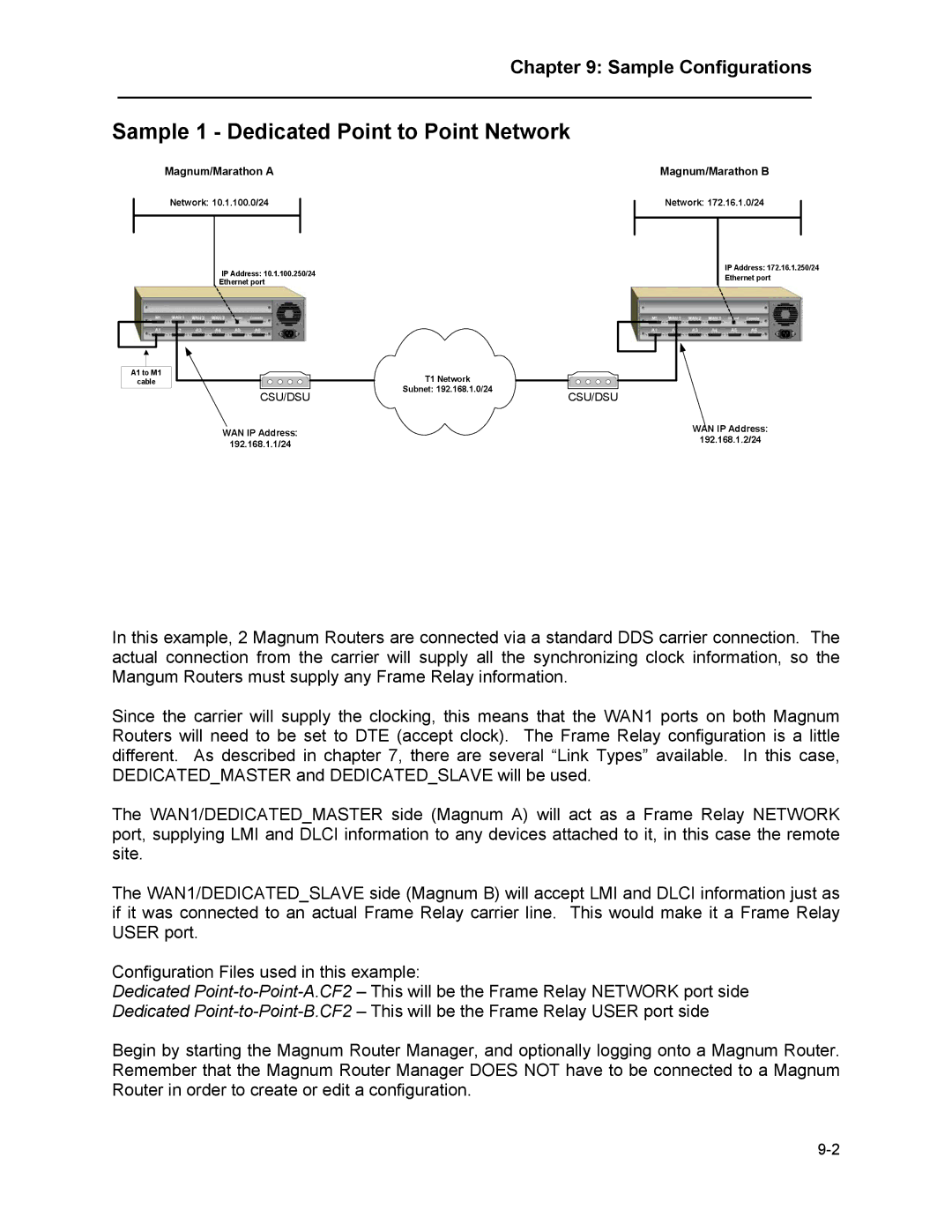
Sample 1 - Dedicated Point to Point Network
Magnum/Marathon A
Network: 10.1.100.0/24
IP Address: 10.1.100.250/24
Ethernet port
A1 to M1 | T1 Network |
|
cable |
| |
CSU/DSU | Subnet: 192.168.1.0/24 | CSU/DSU |
|
WAN IP Address:
192.168.1.1/24
Magnum/Marathon B
Network: 172.16.1.0/24
IP Address: 172.16.1.250/24
Ethernet port
WAN IP Address:
192.168.1.2/24
In this example, 2 Magnum Routers are connected via a standard DDS carrier connection. The actual connection from the carrier will supply all the synchronizing clock information, so the Mangum Routers must supply any Frame Relay information.
Since the carrier will supply the clocking, this means that the WAN1 ports on both Magnum Routers will need to be set to DTE (accept clock). The Frame Relay configuration is a little different. As described in chapter 7, there are several “Link Types” available. In this case, DEDICATED_MASTER and DEDICATED_SLAVE will be used.
The WAN1/DEDICATED_MASTER side (Magnum A) will act as a Frame Relay NETWORK port, supplying LMI and DLCI information to any devices attached to it, in this case the remote site.
The WAN1/DEDICATED_SLAVE side (Magnum B) will accept LMI and DLCI information just as if it was connected to an actual Frame Relay carrier line. This would make it a Frame Relay USER port.
Configuration Files used in this example:
Dedicated
Begin by starting the Magnum Router Manager, and optionally logging onto a Magnum Router. Remember that the Magnum Router Manager DOES NOT have to be connected to a Magnum Router in order to create or edit a configuration.