Preparing the installation site | 2 |
5.One device in the stack will operate as the Active Controller, one will operate as Standby Controller, with the rest of the units operating as stack members. For information about how to configure your stack, see the PowerConnect
PowerConnect B-FCX624 and PowerConnect B-FCX648 devices
Figure 23 and Figure 24 show how stacking cables are connected between PowerConnect B-FCX624 and PowerConnect B-FCX648 devices in a stack. The connection is based on 10 Gbps SFP+ using LC-LC MM Fiber cables. These devices support linear and ring stack topologies with the optional SFP+ modules installed, and can also operate in standalone mode.
NOTE
PowerConnect B-FCX624 and PowerConnect B-FCX648 devices must have a 4-port 10 Gbps SFP+ module (optional) installed to operate in a stack.
Figure 25 shows a stack containing PowerConnect B-FCX624 , PowerConnect B-FCX648 devices and another PowerConnect B-FCX device. Using PowerConnect B-FCX624 and PowerConnect B-FCX648 devices in this type of mixed stack requires your to reconfigure the default stacking ports on the other PowerConnect B-FCX device. For more information, see the FastIron Configuration Guide.
You can form a stack containing up to eight PowerConnect B-FCX624 and PowerConnect B-FCX648 units. To connect switches in a stack, perform the following steps:
1.Plug one end of an LC-LC MM Fiber cable into one of the SFP+ stacking ports of the top unit.
2.Plug the other end of the cable into one of the stacking ports of the next unit.
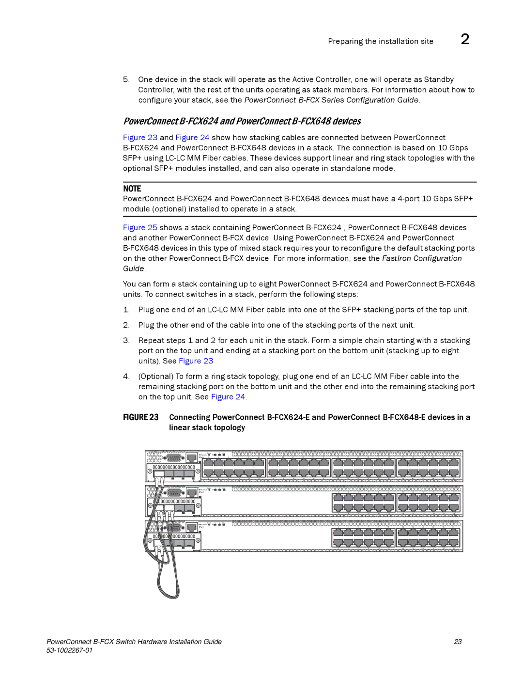
3.Repeat steps 1 and 2 for each unit in the stack. Form a simple chain starting with a stacking port on the top unit and ending at a stacking port on the bottom unit (stacking up to eight units). See Figure 23
4.(Optional) To form a ring stack topology, plug one end of an LC-LC MM Fiber cable into the remaining stacking port on the bottom unit and the other end into the remaining stacking port on the top unit. See Figure 24.
FIGURE 23 Connecting PowerConnect B-FCX624-E and PowerConnect B-FCX648-E devices in a linear stack topology
| Reset | 1 | 2 | Diag |
|
|
|
|
|
|
|
|
|
|
|
|
|
|
|
|
|
|
|
|
|
Console |
| PS |
|
|
|
|
|
|
|
|
|
|
|
|
|
|
|
|
|
|
|
|
|
|
|
Mgmt | 1 |
| 3 | 5 | 7 | 9 | 11 | 13 | 15 | 17 | 19 | 21 | 23 | 25 | 27 | 29 | 31 | 33 | 35 | 37 | 39 | 41 | 43 | 45 | 47 |
2 |
| 4 | 6 | 8 | 10 | 12 | 14 | 16 | 18 | 20 | 22 | 24 | 26 | 28 | 30 | 32 | 34 | 36 | 38 | 40 | 42 | 44 | 46 | 48 |
Reset | 1 | 2 | Diag |
|
|
|
|
|
|
|
|
|
|
|
|
|
|
|
|
|
|
|
|
|
Console | PS |
|
|
|
|
|
|
|
|
|
|
|
|
|
|
|
|
|
|
|
|
|
|
|
Mgmt |
|
|
|
|
|
|
|
|
|
|
|
| 1 | 3 | 5 | 7 | 9 | 11 | 13 | 15 | 17 | 19 | 21 | 23 |
|
|
|
|
|
|
|
|
|
|
|
|
| 2 | 4 | 6 | 8 | 10 | 12 | 14 | 16 | 18 | 20 | 22 | 24 |
Reset | 1 | 2 | Diag |
|
|
|
|
|
|
|
|
|
|
|
Console | PS |
|
|
|
|
|
|
|
|
|
|
|
|
|
Mgmt |
|
| 1 | 3 | 5 | 7 | 9 | 11 | 13 | 15 | 17 | 19 | 21 | 23 |
|
|
| 2 | 4 | 6 | 8 | 10 | 12 | 14 | 16 | 18 | 20 | 22 | 24 |
PowerConnect | 23 |
|