2 Installing or replacing fan trays on PowerConnect
Installing or replacing fan trays on PowerConnect
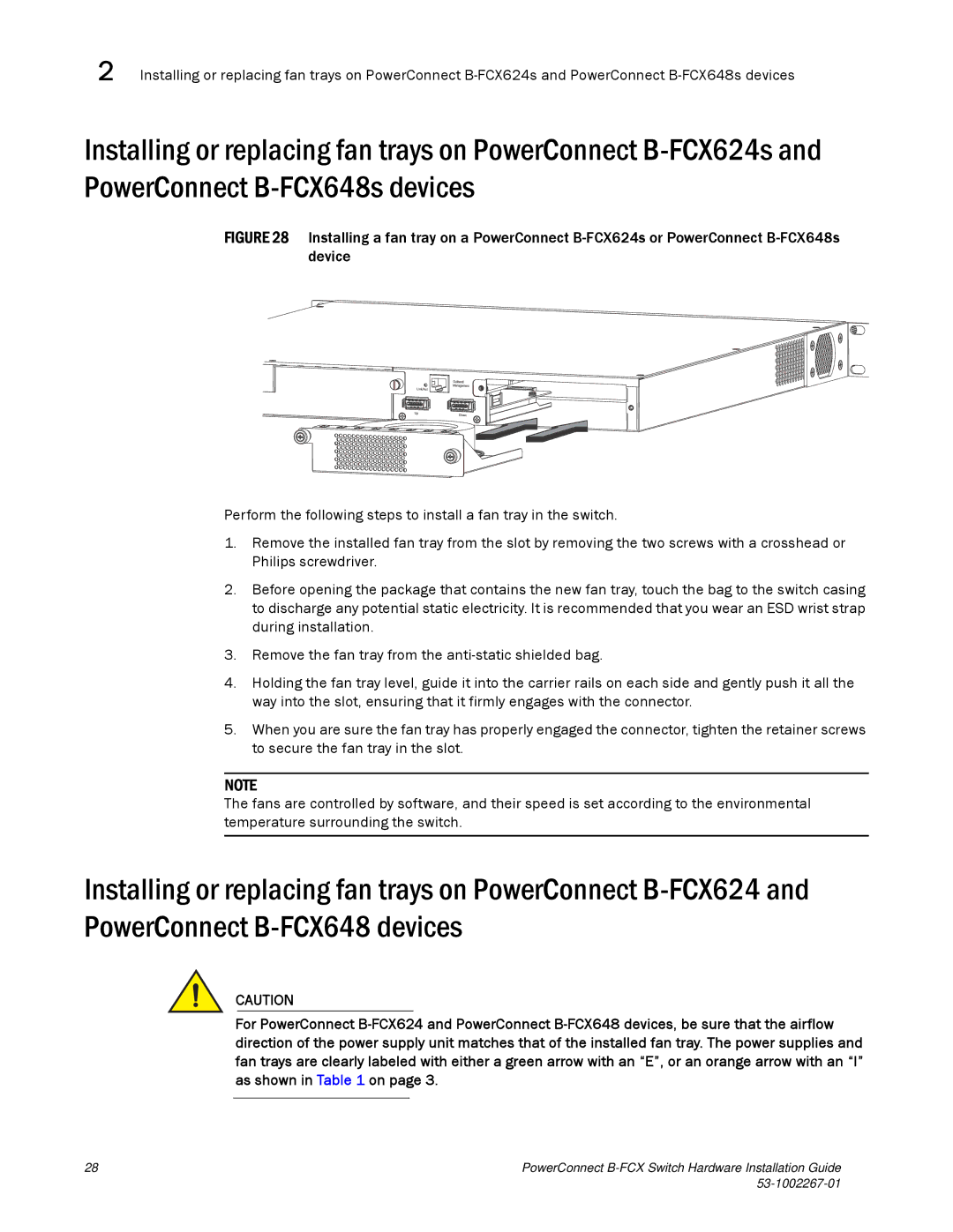
FIGURE 28 Installing a fan tray on a PowerConnect B-FCX624s or PowerConnect B-FCX648s device
Perform the following steps to install a fan tray in the switch.
1.Remove the installed fan tray from the slot by removing the two screws with a crosshead or Philips screwdriver.
2.Before opening the package that contains the new fan tray, touch the bag to the switch casing to discharge any potential static electricity. It is recommended that you wear an ESD wrist strap during installation.
3.Remove the fan tray from the anti-static shielded bag.
4.Holding the fan tray level, guide it into the carrier rails on each side and gently push it all the way into the slot, ensuring that it firmly engages with the connector.
5.When you are sure the fan tray has properly engaged the connector, tighten the retainer screws to secure the fan tray in the slot.
NOTE
The fans are controlled by software, and their speed is set according to the environmental temperature surrounding the switch.
Installing or replacing fan trays on PowerConnect
CAUTION
For PowerConnect
28 | PowerConnect |
|