1 Hardware features
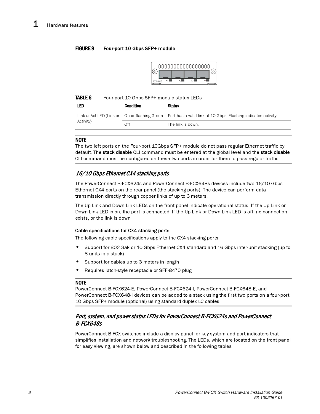
FIGURE 9 Four-port 10 Gbps SFP+ module
X2 | X3 | X4 | ||||
|
|
|
|
|
|
|
TABLE 6 |
| ||
|
|
|
|
LED |
| Condition | Status |
|
|
| |
Link or Act LED (Link or On or flashing Green | Port has a valid link at 10 Gbps. Flashing indicates activity. | ||
Activity) |
|
|
|
| Off | The link is down. | |
|
| ||
|
|
|
|
NOTE
The two left ports on the
16/10 Gbps Ethernet CX4 stacking ports
The PowerConnect
The Up Link and Down Link LEDs on the front panel indicate operational status. If the Up Link or Down Link LED is on, the port is connected. If the Up Link or Down Link LED is off, no connection exists, or the link is down.
Cable specifications for CX4 stacking ports
The following cable specifications apply to the CX4 stacking ports:
•Support for 802.3ak or 10 Gbps Ethernet CX4 standard and 16 Gbps
•Support for cables up to 3 meters in length
•Requires
NOTE
PowerConnect
Port, system, and power status LEDs for PowerConnect
PowerConnect
8 | PowerConnect |
|
