2 Powering on the system
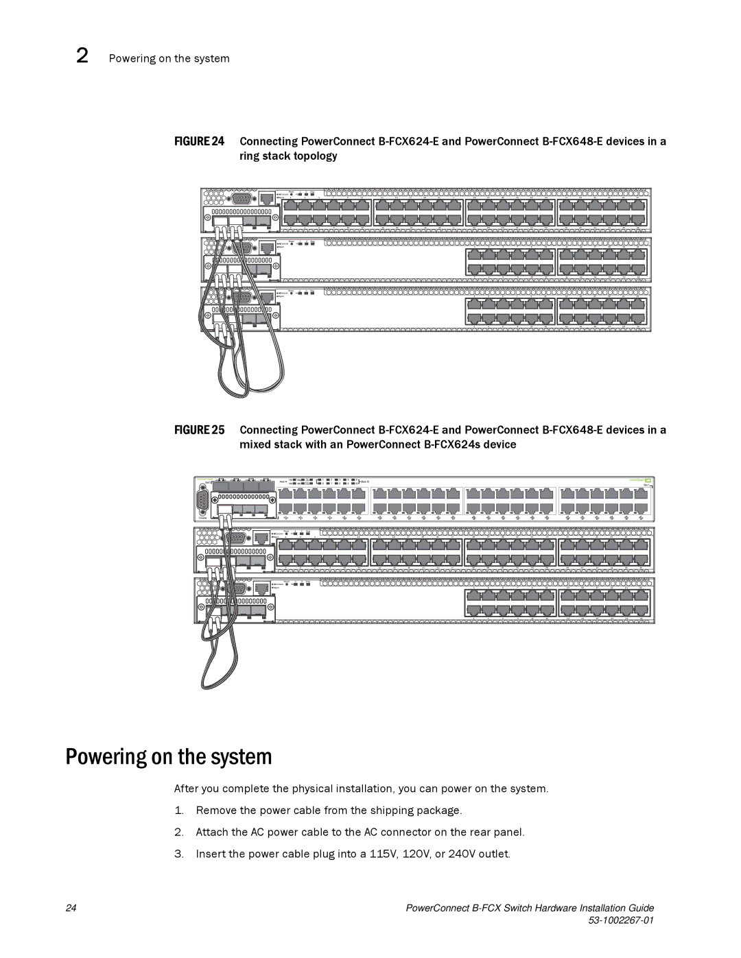
FIGURE 24 Connecting PowerConnect B-FCX624-E and PowerConnect B-FCX648-E devices in a ring stack topology
| Reset | 1 | 2 | Diag |
|
|
|
|
|
|
|
|
|
|
|
|
|
|
|
|
|
|
|
|
|
Console |
| PS |
|
|
|
|
|
|
|
|
|
|
|
|
|
|
|
|
|
|
|
|
|
|
|
Mgmt | 1 |
| 3 | 5 | 7 | 9 | 11 | 13 | 15 | 17 | 19 | 21 | 23 | 25 | 27 | 29 | 31 | 33 | 35 | 37 | 39 | 41 | 43 | 45 | 47 |
2 |
| 4 | 6 | 8 | 10 | 12 | 14 | 16 | 18 | 20 | 22 | 24 | 26 | 28 | 30 | 32 | 34 | 36 | 38 | 40 | 42 | 44 | 46 | 48 |
Reset | 1 | 2 | Diag |
|
|
|
|
|
|
|
|
|
|
|
|
|
|
|
|
|
|
|
|
|
Console | PS |
|
|
|
|
|
|
|
|
|
|
|
|
|
|
|
|
|
|
|
|
|
|
|
Mgmt |
|
|
|
|
|
|
|
|
|
|
|
| 1 | 3 | 5 | 7 | 9 | 11 | 13 | 15 | 17 | 19 | 21 | 23 |
|
|
|
|
|
|
|
|
|
|
|
|
| 2 | 4 | 6 | 8 | 10 | 12 | 14 | 16 | 18 | 20 | 22 | 24 |
Reset | 1 | 2 | Diag |
|
|
|
|
|
|
|
|
|
|
|
Console | PS |
|
|
|
|
|
|
|
|
|
|
|
|
|
Mgmt |
|
| 1 | 3 | 5 | 7 | 9 | 11 | 13 | 15 | 17 | 19 | 21 | 23 |
|
|
| 2 | 4 | 6 | 8 | 10 | 12 | 14 | 16 | 18 | 20 | 22 | 24 |
FIGURE 25 Connecting PowerConnect B-FCX624-E and PowerConnect B-FCX648-E devices in a mixed stack with an PowerConnect B-FCX624s device
| Reset | 1 | 2 | Diag |
|
|
|
|
|
|
|
|
|
|
|
|
|
|
|
|
|
|
|
|
|
Console |
| PS |
|
|
|
|
|
|
|
|
|
|
|
|
|
|
|
|
|
|
|
|
|
|
|
Mgmt | 1 |
| 3 | 5 | 7 | 9 | 11 | 13 | 15 | 17 | 19 | 21 | 23 | 25 | 27 | 29 | 31 | 33 | 35 | 37 | 39 | 41 | 43 | 45 | 47 |
2 |
| 4 | 6 | 8 | 10 | 12 | 14 | 16 | 18 | 20 | 22 | 24 | 26 | 28 | 30 | 32 | 34 | 36 | 38 | 40 | 42 | 44 | 46 | 48 |
Reset | 1 | 2 | Diag |
|
|
|
|
|
|
|
|
|
|
|
|
|
|
|
|
|
|
|
|
|
Console | PS |
|
|
|
|
|
|
|
|
|
|
|
|
|
|
|
|
|
|
|
|
|
|
|
Mgmt |
|
|
|
|
|
|
|
|
|
|
|
| 1 | 3 | 5 | 7 | 9 | 11 | 13 | 15 | 17 | 19 | 21 | 23 |
|
|
|
|
|
|
|
|
|
|
|
|
| 2 | 4 | 6 | 8 | 10 | 12 | 14 | 16 | 18 | 20 | 22 | 24 |
Powering on the system
After you complete the physical installation, you can power on the system.
1.Remove the power cable from the shipping package.
2.Attach the AC power cable to the AC connector on the rear panel.
3.Insert the power cable plug into a 115V, 120V, or 240V outlet.
24 | PowerConnect |
|