Preparing the installation site | 2 |
FIGURE 20 Attaching the brackets for PowerConnect B-FCX624 and PowerConnect B-FCX648
3.Install retainer nuts into the non-threaded holes. And use 10-32 screws to fasten brackets into the rack. Attach the device in the rack as illustrated in Figure 21.
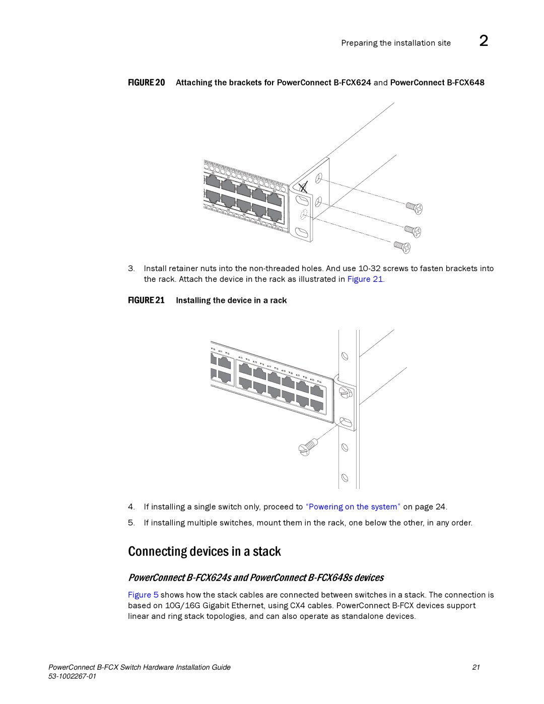
FIGURE 21 Installing the device in a rack
4.If installing a single switch only, proceed to “Powering on the system” on page 24.
5.If installing multiple switches, mount them in the rack, one below the other, in any order.
Connecting devices in a stack
PowerConnect B-FCX624s and PowerConnect B-FCX648s devices
Figure 5 shows how the stack cables are connected between switches in a stack. The connection is based on 10G/16G Gigabit Ethernet, using CX4 cables. PowerConnect B-FCX devices support linear and ring stack topologies, and can also operate as standalone devices.
PowerConnect | 21 |
|