2 Preparing the installation site
In a linear stack topology there is a single stack cable connection between each switch that carries
You can form a stack containing up to eight PowerConnect
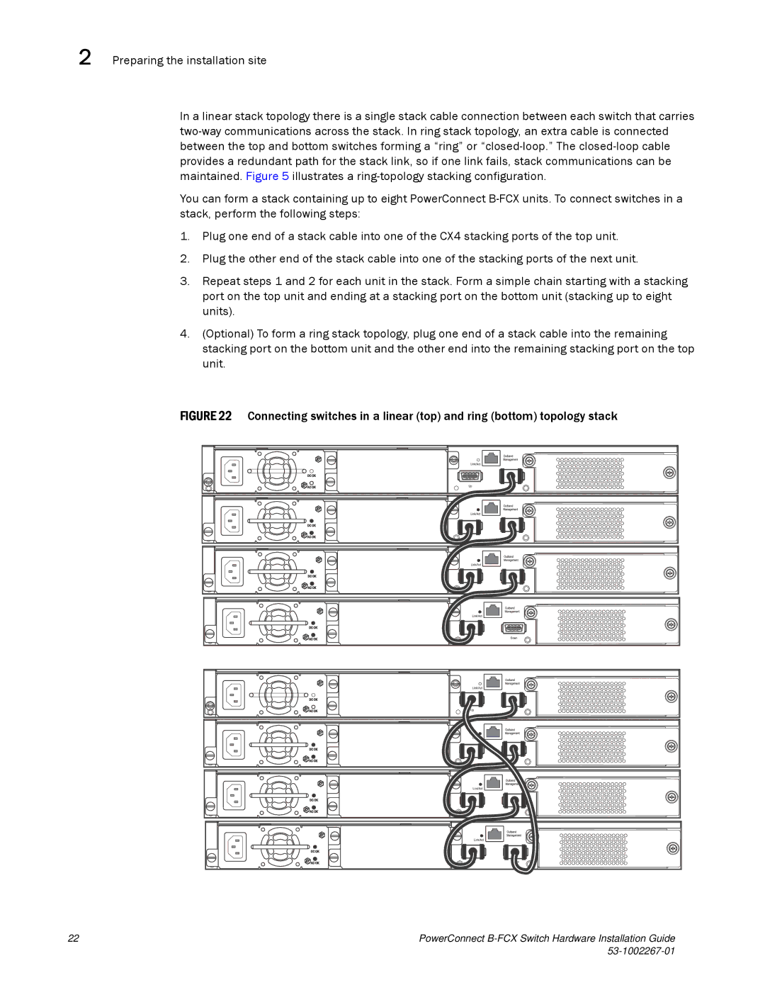
1.Plug one end of a stack cable into one of the CX4 stacking ports of the top unit.
2.Plug the other end of the stack cable into one of the stacking ports of the next unit.
3.Repeat steps 1 and 2 for each unit in the stack. Form a simple chain starting with a stacking port on the top unit and ending at a stacking port on the bottom unit (stacking up to eight units).
4.(Optional) To form a ring stack topology, plug one end of a stack cable into the remaining stacking port on the bottom unit and the other end into the remaining stacking port on the top unit.
FIGURE 22 Connecting switches in a linear (top) and ring (bottom) topology stack
22 | PowerConnect |
|