1 | Hardware features |
|
|
| |
|
| TABLE 8 | System status LEDs |
| |
|
| LED |
| Condition | Status |
|
|
|
|
|
|
|
| PS1 |
| Green | Power supply is operating normally. |
|
| PS2 |
|
|
|
|
|
| Amber | Power supply fault. | |
|
| (Power Supply | |||
|
|
|
| ||
|
| Status) |
| Off | Power off or failure. |
|
|
|
|
|
|
|
| Diag |
| Flashing Green | System |
|
| (Diagnostic) |
|
|
|
|
|
| Green | System | |
|
|
|
| ||
|
|
|
|
|
|
|
|
|
| Amber | System |
|
|
|
|
| interface fault.) |
|
|
|
|
|
|
|
| A or S |
| Green | The device is the Active controller. If this LED is flashing green, the |
|
| (Active or Standby) |
| system is initializing. | |
|
|
|
|
|
|
|
|
|
| Amber | Indicates the device is the Standby controller. |
|
|
|
|
|
|
|
|
|
| Off | Device is operating as a stack member, or is in standalone mode. |
|
|
|
|
| |
|
| Up Link or Down | Green | Uplink is operating normally. | |
|
| Link (Stacking |
|
| |
|
| Off | Uplink has failed or there is no link. | ||
|
| uplink or downlink | |||
|
|
|
| ||
|
| port status) |
|
|
|
|
|
|
|
|
|
|
| Stack ID |
| Green | Indicates the device stack ID. |
|
|
|
|
|
|
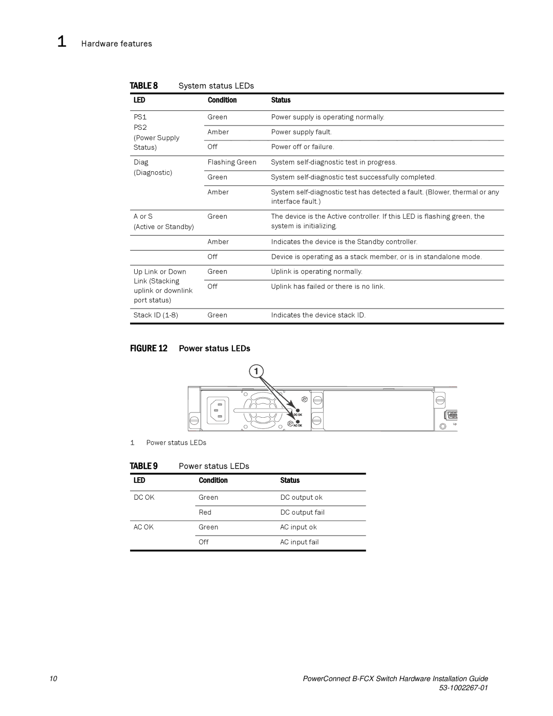
FIGURE 12 Power status LEDs
1
1 Power status LEDs
TABLE 9 | Power status LEDs |
| |
LED |
| Condition | Status |
|
|
|
|
DC OK |
| Green | DC output ok |
|
|
|
|
|
| Red | DC output fail |
|
|
|
|
AC OK |
| Green | AC input ok |
|
|
|
|
|
| Off | AC input fail |
|
|
|
|
10 | PowerConnect |
|