5 Hardware specifications
Storage environment
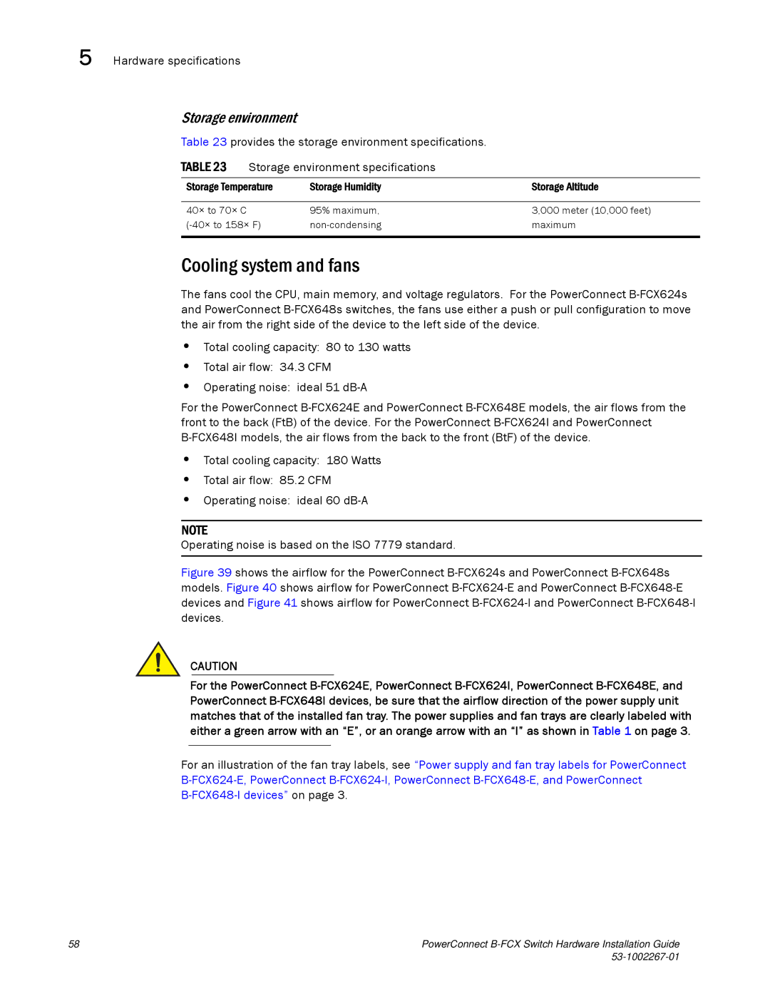
Table 23 provides the storage environment specifications.
TABLE 23 Storage environment specifications
Storage Temperature | Storage Humidity | Storage Altitude |
|
|
|
40× to 70× C | 95% maximum, | 3,000 meter (10,000 feet) |
maximum | ||
|
|
|
Cooling system and fans
The fans cool the CPU, main memory, and voltage regulators. For the PowerConnect
•Total cooling capacity: 80 to 130 watts
•Total air flow: 34.3 CFM
•Operating noise: ideal 51
For the PowerConnect
•Total cooling capacity: 180 Watts
•Total air flow: 85.2 CFM
•Operating noise: ideal 60
NOTE
Operating noise is based on the ISO 7779 standard.
Figure 39 shows the airflow for the PowerConnect B-FCX624s and PowerConnect B-FCX648s models. Figure 40 shows airflow for PowerConnect B-FCX624-E and PowerConnect B-FCX648-E devices and Figure 41 shows airflow for PowerConnect B-FCX624-I and PowerConnect B-FCX648-I devices.
CAUTION
For the PowerConnect
For an illustration of the fan tray labels, see “Power supply and fan tray labels for PowerConnect
58 | PowerConnect |
|
