Hardware features | 1 |
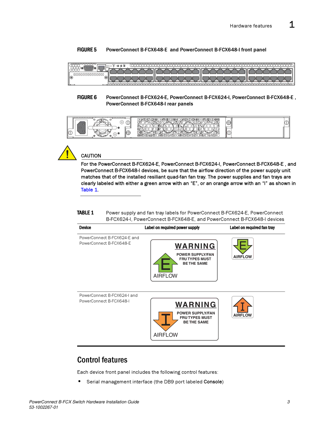
FIGURE 5 PowerConnect B-FCX648-E and PowerConnect B-FCX648-I front panel
| Reset | 1 | 2 | Diag |
|
|
|
|
|
|
|
|
|
|
|
|
|
|
|
|
|
|
|
|
|
Console |
| PS |
|
|
|
|
|
|
|
|
|
|
|
|
|
|
|
|
|
|
|
|
|
|
|
Mgmt | 1 |
| 3 | 5 | 7 | 9 | 11 | 13 | 15 | 17 | 19 | 21 | 23 | 25 | 27 | 29 | 31 | 33 | 35 | 37 | 39 | 41 | 43 | 45 | 47 |
| 2 |
| 4 | 6 | 8 | 10 | 12 | 14 | 16 | 18 | 20 | 22 | 24 | 26 | 28 | 30 | 32 | 34 | 36 | 38 | 40 | 42 | 44 | 46 | 48 |
FIGURE 6 PowerConnect B-FCX624-E, PowerConnect B-FCX624-I, PowerConnect B-FCX648-E , PowerConnect B-FCX648-I rear panels
CAUTION
For the PowerConnect
TABLE 1 Power supply and fan tray labels for PowerConnect
Device | Label on required power supply | Label on required fan tray | |||
|
|
|
|
|
|
PowerConnect |
|
|
|
|
|
PowerConnect |
|
|
|
|
|
WARNING |
| E |
| ||
|
|
| |||
|
|
|
|
| |
| POWER SUPPLY/FAN | AIRFLOW | |||
|
| ||||
EBE THE SAMEFRU TYPES MUST
AIRFLOW
PowerConnect |
|
|
|
|
|
|
|
PowerConnect |
|
| WARNING |
|
|
|
|
|
|
|
|
|
|
| |
|
|
| POWER SUPPLY/FAN |
|
|
|
|
|
|
| AIRFLOW | ||||
|
|
| FRU TYPES MUST | ||||
|
|
|
|
|
|
| |
|
|
| BE THE SAME |
|
|
|
|
AIRFLOW
Control features
Each device front panel includes the following control features:
•Serial management interface (the DB9 port labeled Console)
PowerConnect | 3 |
|