VFD-F Series

NOTE

1.Please select the brake unit and/or brake resistor according to the table. “-“ means no Delta product. Please use the brake unit according to the Equivalent Resistor Value.

2.If damage to the drive or other equipment is due to the fact that the brake resistors and the brake modules in use are not provided by Delta, the warranty will be void.

3.Take into consideration the safety of the environment when installing the brake resistors.

4.If the minimum resistance value is to be utilized, consult local dealers for the calculation of the power in Watt.

5.Please select thermal relay trip contact to prevent resistor over load. Use the contact to switch power off to the AC motor drive!

6.When using more than 2 brake units, equivalent resistor value of parallel brake unit can’t be less than the value in the column “Minimum Equivalent Resistor Value for Each AC Drive” (the right-most column in the table).

7.Please read the wiring information in the user manual of the brake unit thoroughly prior to installation and operation.

8.In applications with brake resistor or brake unit, Pr.06-00 (Over-voltage stall prevention) must be disabled. And Pr.08-18 (AVR function) shall not be used.

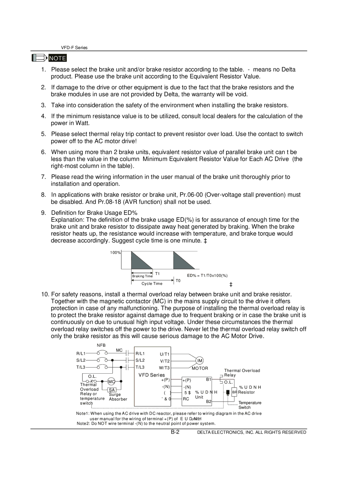
9.Definition for Brake Usage ED%

Explanation: The definition of the brake usage ED(%) is for assurance of enough time for the brake unit and brake resistor to dissipate away heat generated by braking. When the brake resistor heats up, the resistance would increase with temperature, and brake torque would decrease accordingly. Suggest cycle time is one minute.

100%


T1


ED% = T1/T0x100(%)


Braking Time


T0


Cycle Time


10.For safety reasons, install a thermal overload relay between brake unit and brake resistor. Together with the magnetic contactor (MC) in the mains supply circuit to the drive it offers protection in case of any malfunctioning. The purpose of installing the thermal overload relay is to protect the brake resistor against damage due to frequent braking or in case the brake unit is continuously on due to unusual high input voltage. Under these circumstances the thermal overload relay switches off the power to the drive. Never let the thermal overload relay switch off only the brake resistor as this will cause serious damage to the AC Motor Drive.

NFB

R/L1

S/L2

T/L3

O.L.

Thermal

Overload Relay or temperature switch

MC

MC

SA

Surge

Absorber

R/L1

U/T1


S/L2

V/T2

IM

T/L3

W/T3

MOTOR

VFD Series


B1

+(P)


+(P)


-(N)


-(N)

Brake


E.F


RA

DCM


RC

Unit


B2


Thermal Overload Relay

O.L.

Brake

BR Resistor

Temperature

Switch

Note1: When using the AC drive with DC reactor, please refer to wiring diagram in the AC drive user manual for the wiring of terminal +(P) of brake unit.

Note2: Do NOT wire terminal -(N) to the neutral point of power system.

B-2

DELTA ELECTRONICS, INC. ALL RIGHTS RESERVED

Page 137
Image 137
Delta Electronics VFD-F Series manual VFD Series

VFD-F Series specifications

Delta Electronics has established itself as a leader in the production of Variable Frequency Drives (VFDs), and the VFD-F Series exemplifies their commitment to innovation and efficiency in motor control solutions. Designed for a wide range of applications, the VFD-F Series ensures seamless operation in various industrial settings, from pumps and fans to conveyor systems and HVAC equipment.

One of the primary features of the VFD-F Series is its compact design, which allows for easy integration into existing systems without consuming excessive space. This makes it an ideal choice for projects where space is limited. The series also boasts a high IP20 protection rating, ensuring that the drives are safeguarded against dust and accidental contact, contributing to their reliability and longevity.

The VFD-F Series utilizes advanced control technologies, including vector control and scalar control. Vector control provides precise torque and speed control, allowing for optimal performance under varying load conditions. This is particularly advantageous in applications requiring high accuracy, such as robotics and machine tools. The scalar control mode, on the other hand, is simpler and suitable for applications where precise control is not as critical.

Energy efficiency is a hallmark of the VFD-F Series. By allowing users to control motor speed and torque based on the actual demand, these drives can significantly reduce energy consumption compared to traditional fixed-speed motors. Coupled with Delta's energy-saving algorithms, the VFD-F Series not only promotes sustainable operation but also helps lower operational costs.

Another key characteristic of the VFD-F Series is its user-friendly interface. The intuitive control panel and programmable features enable quick setup and adjustments. Furthermore, the series supports multiple communication protocols, including Modbus, CANopen, and EtherCAT, which facilitate integration into various automation systems.

Safety features are paramount in the design of the VFD-F Series. It includes built-in protections against over-voltage, over-current, and overheating, ensuring safe operation in demanding environments. Additionally, its compliance with international safety standards underlines its reliability and robustness.

In summary, Delta Electronics' VFD-F Series stands out with its compact design, advanced control technologies, energy efficiency, user-friendly interface, and integral safety features. These characteristics make it a formidable solution for industries seeking high-performance motor control while maximizing efficiency and safety. As the demand for integrated and intelligent automation solutions grows, the VFD-F Series is well-positioned to meet these challenges head-on, reinforcing Delta Electronics’ reputation as a pioneer in the field.