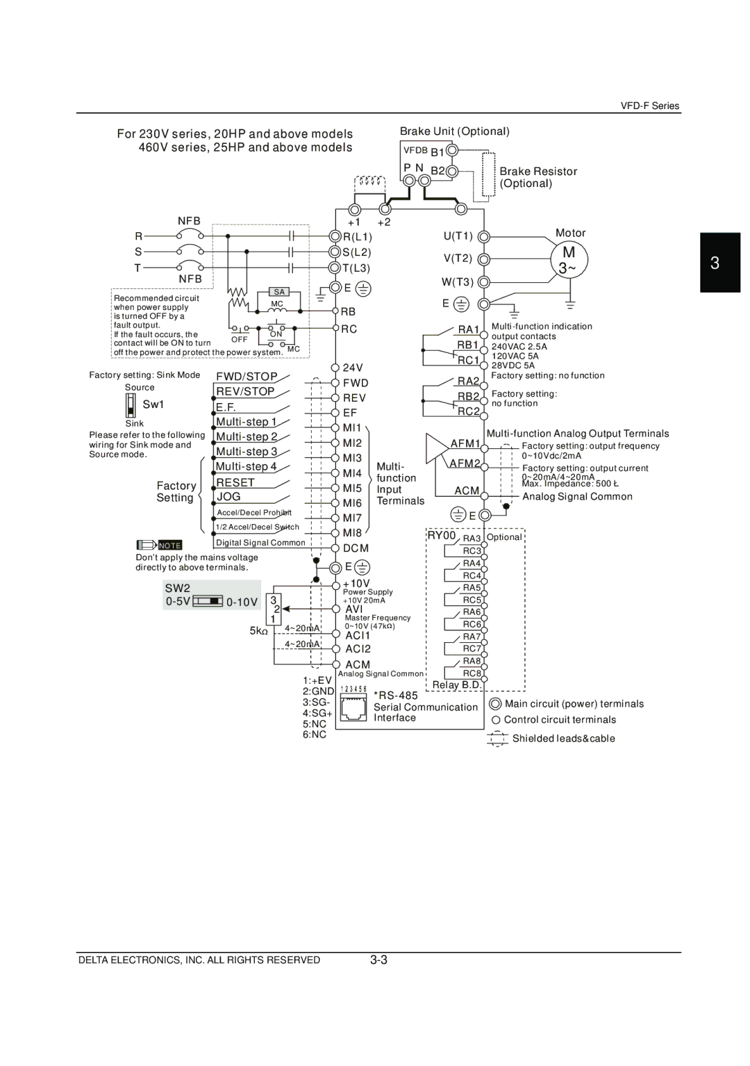
VFD-F Series specifications
Delta Electronics has established itself as a leader in the production of Variable Frequency Drives (VFDs), and the VFD-F Series exemplifies their commitment to innovation and efficiency in motor control solutions. Designed for a wide range of applications, the VFD-F Series ensures seamless operation in various industrial settings, from pumps and fans to conveyor systems and HVAC equipment.One of the primary features of the VFD-F Series is its compact design, which allows for easy integration into existing systems without consuming excessive space. This makes it an ideal choice for projects where space is limited. The series also boasts a high IP20 protection rating, ensuring that the drives are safeguarded against dust and accidental contact, contributing to their reliability and longevity.
The VFD-F Series utilizes advanced control technologies, including vector control and scalar control. Vector control provides precise torque and speed control, allowing for optimal performance under varying load conditions. This is particularly advantageous in applications requiring high accuracy, such as robotics and machine tools. The scalar control mode, on the other hand, is simpler and suitable for applications where precise control is not as critical.
Energy efficiency is a hallmark of the VFD-F Series. By allowing users to control motor speed and torque based on the actual demand, these drives can significantly reduce energy consumption compared to traditional fixed-speed motors. Coupled with Delta's energy-saving algorithms, the VFD-F Series not only promotes sustainable operation but also helps lower operational costs.
Another key characteristic of the VFD-F Series is its user-friendly interface. The intuitive control panel and programmable features enable quick setup and adjustments. Furthermore, the series supports multiple communication protocols, including Modbus, CANopen, and EtherCAT, which facilitate integration into various automation systems.
Safety features are paramount in the design of the VFD-F Series. It includes built-in protections against over-voltage, over-current, and overheating, ensuring safe operation in demanding environments. Additionally, its compliance with international safety standards underlines its reliability and robustness.
In summary, Delta Electronics' VFD-F Series stands out with its compact design, advanced control technologies, energy efficiency, user-friendly interface, and integral safety features. These characteristics make it a formidable solution for industries seeking high-performance motor control while maximizing efficiency and safety. As the demand for integrated and intelligent automation solutions grows, the VFD-F Series is well-positioned to meet these challenges head-on, reinforcing Delta Electronics’ reputation as a pioneer in the field.

