Making Two-Channel Call Transfers (Tromboning)
channel provides silence generation on its output). After playback is completed, the application can
The following series of illustrations demonstrate the changes.
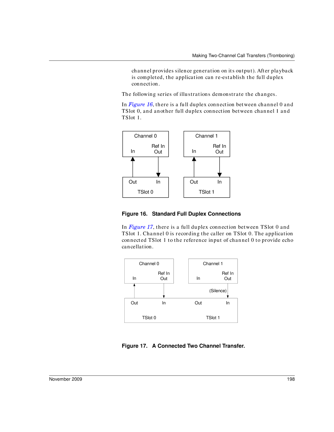
In Figure 16, there is a full duplex connection between channel 0 and TSlot 0, and another full duplex connection between channel 1 and TSlot 1.
Channel 0
Ref In
In Out
Out In
TSlot 0
Channel 1
Ref In
In Out
Out In
TSlot 1
Figure 16. Standard Full Duplex Connections
In Figure 17, there is a full duplex connection between TSlot 0 and TSlot 1. Channel 0 is recording the caller on TSlot 0. The application connected TSlot 1 to the reference input of channel 0 to provide echo cancellation.
Channel 0
Ref In
InOut
Channel 1
Ref In
InOut
|
|
|
|
|
| (Silence) |
|
|
|
|
|
|
|
| |
|
|
|
|
|
|
|
|
|
|
|
|
|
|
|
|
Out | In | Out | In | ||||
|
| TSlot 0 |
| TSlot 1 | |||
|
|
|
|
|
|
|
|
Figure 17. A Connected Two Channel Transfer.
November 2009 | 198 |