Rosemount 2051 Wireless Pressure Transmitters
Page
Reference Manual
Rosemount 2051 Wireless Pressure, Flow, and Level Solutions
Explosions could result in death or serious injury
Iii
Reference Manual
Contents
Table of Contents Reference Manual
Installation
Commissioning
Operation and maintenance
Troubleshooting
Appendix B Product Certifications
Appendix a Specifications Reference Data
Appendix D Network design best practices
Appendix C Field Communicator Menu Trees and Fast Keys
Table of Contents Reference Manual
Rosemount 2051T in-line Pressure Transmitter
Using this manual
Models covered
Rosemount 2051C Coplanar Pressure Transmitter
Introduction Reference Manual
Rosemount 2051L Level Transmitter
Rosemount 2051CF Flowmeters
WirelessHART installation flowchart
WirelessHART installation flowchart
LCD Display
Transmitter overview
Antenna position
Considerations before transmitter installation
Wireless considerations
Power up sequence
Electrical
Mechanical
Environmental
Service support
Temperature effects
Product Recycling/Disposal
Overview
Safety messages
Configuration Reference Manual
Required bench top configuration
AMS Wireless Configurator
Bench hook-up
Basic setup
Connection diagrams
Set device tag
Join device to network
Configure update rate
Select 1 Guided Setup Select 3 Join Device to Network
Select 1 Guided Setup Select 4 Configure Update Rate
Set process variable units
Configure for Pressure
Remove Power Module
Select 2 Manual Setup Select 2 Pressure
Variable Mapping
Re-mapping using a Field Communicator
Re-mapping using AMS Device Manager
Set range points
Set transmitter percent of range transfer function
Setting transmitter output with a Field Communicator
Setting transmitter output with AMS Device Manager
Configuring Scaled Variable using AMS Device Manager
Configure for Level and Flow
Configuring scaled variable
Configuring Scaled Variable using a Field Communicator
DP Flow example
Scaled Variable Configuration for Tank Application
DP Level Example
Scaled Variable Configuration for Flow Application
Set range points
Review device information
Review configuration data
Select 2 Manual Setup Select 9 Device Information
Review pressure information
Select 2 Variables
Review radio information
Review operating parameters
Select 7 Device Information
Click Manual Setup, select the Display tab
Configuring the LCD display
Configuring LCD display with a Field Communicator
Configuring LCD display with AMS Device Manager
Damping
Detailed transmitter setup
Configure process alerts
Select 1 Guided Setup
Write protect
Diagnostics and service
Join status
Device reset
Number of available neighbors
Field Communicator
Saving, Recalling, and Cloning Configuration Data
Advanced Functions for Hart Protocol
AMS creating a Reusable Copy
AMS Applying a User Configuration
Section Installation
Installation Reference Manual
Considerations
Installation considerations
Reference Manual Installation
Internal antenna position
Steam service
Mechanical considerations
Environmental considerations
Draft range considerations
Installation Flowchart
Reference side filtering
Reducing process noise
Output damping
Circuit side of electronics housing
Installation procedures
Consider housing rotation
Power Module side of electronics housing
Mounting brackets
Environmental seal for housing
Mount the transmitter
Mounting brackets
Mounting bracket option code B4
Flange bolts
Bolt Material Initial Torque Value Final Torque Value
Bolt Installation Torque Values
Description Qty
Size
Panel mounting bracket option codes B2 and B8
Best practices
Impulse piping
Liquid Flow Measurement
Mounting Requirements
Drain/vent valves
Process connections
Coplanar or traditional process connection
Flange adapters
Inline gage transmitter orientation
Inline process connection
13. Power Module
Power Module installation
Installing the LCD display
14. Optional LCD Display
Rosemount 304, 305 and 306 integral manifolds
15. Integral Manifold Designs
Rosemount 305 Integral Manifold installation procedure
16. Bolt tightening pattern
Rosemount 306 Integral Manifold installation procedure
Manifold operation
Rosemount 304 Conventional Manifold installation procedure
Pressure downstream side Transmitter first
Configuration for zeroing
Transmitter to service
To zero the 2051, close Block valve to the low
Test
Close the equalize valve on High pressure upstream Side
Open the equalize valve on Low pressure Downstream side
Transmitter. The manifold is
Now in the proper
Installation
Section
Commissioning Reference Manual
Local Display
Viewing network status
Verifying operation
Function Key Sequence Menu Items
Smart Wireless Gateway
Device Manager
Smart Wireless Gateway Explorer
Smart Wireless Gateway Network Settings
Using the Field Communicator
Reference Manual Commissioning
Configuring transmitter security
Rosemount 2051 Wireless Fast Key Sequence
Hart lock
Configuration Button lock
Configuring Hart Lock using Field Communicator
Configuring Hart Lock using AMS Device Manager
Calibration overview
Operation and maintenance
Transmitter Bench Calibration Tasks Field Calibration Tasks
Operation and Maintenance Reference Manual
Determining necessary Sensor Trims
Recommended Calibration Tasks
Determining calibration frequency
Trimming with configuration buttons
Calculate calibration frequency
HT = URV S/100 x P/1000 x LRV
Trim the pressure signal
Sensor Trim Overview
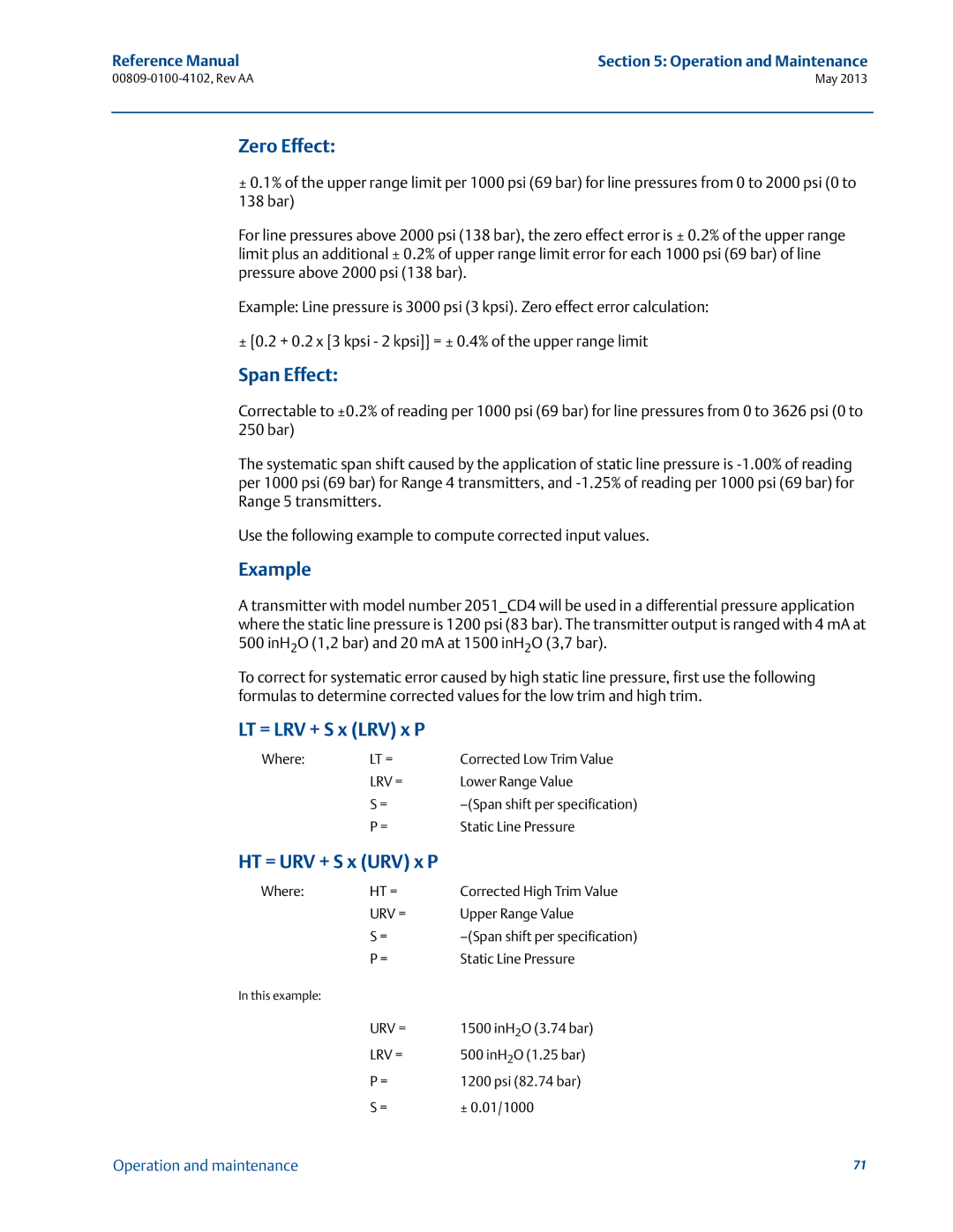
Example
Sensor Trim example
Sensor Trim
Performing a Digital Zero Trim option DZ
Select 5 Maintenance Select 1 Pressure Calibration
Performing a Sensor Trim with a Field Communicator
Performing a Sensor Trim with AMS Device Manager
Compensating for Line Pressure Range 4 and Range
Recall Factory Trim-Sensor Trim
Line Pressure Effect Range 2 and Range
Zero Effect
LT = 500 + 0.01/10005001200 506 inH2O 1.26 bar
Startup Screen Sequence
LCD Screen Messages
S R
13 0
Diagnostic Button Screen Sequence
T w k K n w n
Network Diagnostic Status Screens
C H N G
Operation and maintenance
I l u r
Device Diagnostic Screens
C d e
D i o I l u r
N f g R n
Troubleshooting
Device Status Description Recommended Action
Troubleshooting Reference Manual
Rosemount 2051 Wireless Device Status Information
Check process for possible saturation condition
Reference Manual Troubleshooting
Check the buttons for obstructions
Wireless Network Troubleshooting
Rosemount 2051 Wireless Troubleshooting
Symptom Recommended Actions
Removing from service
Digital output
Performance Specifications
Conformance to specification ±3σ Sigma
Models Standard
Reference Accuracy1
Total Performance
Appendix a Reference Data Reference Manual
Line Pressure Effect per 1000 psi 6,9 MPa1
Long Term Stability
Dynamic Performance
Vibration Effect
Service
Ambient Temperature Effect per 50F 28C
Mounting Position Effects
Range and Sensor Limits
Wireless Self-Organizing Networks
Overpressure limits
Burst pressure limits
Temperature limits
Static pressure limit
2051C Coplanar
Volumetric Displacement
Process Temperature Limits
Humidity Limits
Process-Wetted parts
Physical specifications
Electrical connections
Non-Wetted Parts
Rosemount 2051L Process Wetted Parts
Sensor Module Fill Fluid
Table A-4. Transmitter option weights
Shipping Weights for 2051 Wireless Pressure Transmitter
Table A-2. Transmitter weights without options
Table A-3 L weights without options
Dimensional Drawings
Diameter Gasket Class Size
Table A-5 L Dimensional Specifications
Pipe Process Lower Housing G Class Size Side F NPT
Outside Extension Pipe
Ordering Information
Manifold Assembly59
Housing Material Conduit Entry Size
Wireless Transmit Rate, Operating Frequency and Protocol
Antenna and SmartPower
Product Certifications
Seal Assemblies9
All-Welded Seal Assemblies for high vacuum applications9
Mounting Bracket
Cleaning Process Area
Hardware Adjustments
Software Configuration
Pressure Testing
Toolkit Total System Performance Reports
RC1/4 RC1/2 Process Connection
Max Static Line Pressure
Surface Finish
Options
Process Area8
Zero/Span Adjustment
Wireless Sensor Module
Calibration Certification
Typical Model Number 2051T G 5 X 2A 2 1 P WA3 WP5 B4 M5
Mounting Flange Size, Rating, Material High Side
Model
Code Process Connection Size Material Extension Length
Low Pressure Side Flange Configuration Adapter
Material Traceability Certification Standard
Bolting Material Standard
Calibration Certification Standard
Ring Material Number Size NPT Standard
Hardware Adjustments Standard
Software Configuration Standard
Toolkit Total System Performance Reports Standard
Pipe I.D. Range
Model Product Description
Line Size
Sensor Material
Pipe Material / Mounting Assembly Material
Piping Orientation
Annubar Type
Isolation Valve for Flo-Tap Models
Temperature Measurement
Transmitter Housing Material Conduit Entry Size
Opposite Side Support or Packing Gland
QC1
Fluid and O-ring Options Standard
Primary Element Type
Primary Element Technology
Material Type
Transmitter Housing Material
ANSI/ASME B31.1 ANSI/ASME B31.3 ANSI/ASME B31.8
Bore Size Option
Body Material
Process Connection
Orifice Plate Material
Differential Pressure Ranges
Options
LCD Display Hardware Adjustments Standard
Options
Bolts for flanges and adapters
Configuration buttons
Output information
Display and interface options
Rosemount 2051C Traditional Flange bracket options
Spare parts
Telecommunication compliance
Wireless Certifications
Approved manufacturing locations
European directive information
European certifications
Ordinary location certification for FM
North American certifications
CSA Canadian Standards Association
注意!
134
Field Communicator menu trees
Appendix C Field Communicator Menu Trees and Fast Keys
Appendix C Field Communicator Menu Trees Reference Manual
Guided Setup
137
138
Effective range
Appendix D Network design best practices
Appendix D Network design best practices
Appendix D Network design best practices Reference Manual
Page
Latin America