Oxymitter 4000
Instruction Manual
POWER SUPPLY BOARD
FUSE
| 1 |
| the assembly is secure by gently trying |
|
|
|
| to separate the boards. |
|
| + |
|
|
|
|
| 9. | Reconnect connector J8 to the power |
|
|
|
| supply board. Make sure the connector |
|
| + |
| is secure. |
|
| + | 10. | Holding the J1 connector leads, slide |
|
5A |
|
| ||
|
| the electronic assembly the rest of the |
| |
TIME LAG |
|
|
| |
250VAC |
|
| way into the housing. Align the elec- |
|
| + |
|
| |
| + |
| tronic assembly so that it fits flush on |
|
D | 1 |
| the pins. To ensure that it is flush, |
|
3 |
| gently try to rotate the electronics. If |
| |
G | + |
|
| |
3 |
|
|
| |
1 | + |
|
|
|
96 |
|
|
|
|
9 |
|
|
|
|
REV |
|
| the electronics rotates, repeat the |
|
|
|
| alignment. |
|
| 22220058 | 11. | Reconnect the J1 connector to the mi- |
|
|
|
| ||
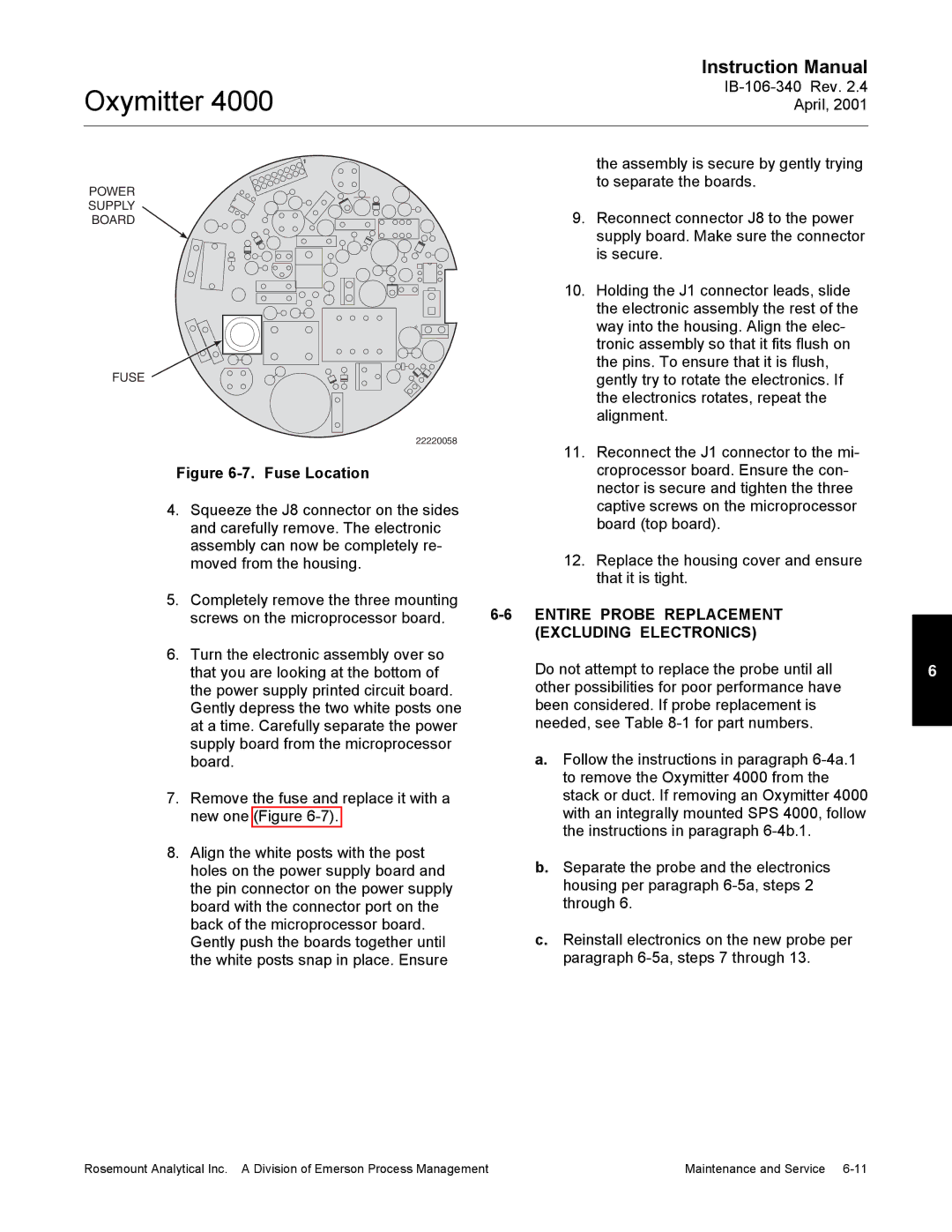
Figure | Fuse Location |
| croprocessor board. Ensure the con- |
|
|
|
| nector is secure and tighten the three |
|
4. Squeeze the J8 connector on the sides |
| captive screws on the microprocessor |
| |
and carefully remove. The electronic |
| board (top board). |
| |
assembly can now be completely re- | 12. | Replace the housing cover and ensure |
| |
moved from the housing. |
| |||
|
|
| that it is tight. |
|
5. Completely remove the three mounting |
|
| ||
screws on the microprocessor board. |
| |||
|
| (EXCLUDING ELECTRONICS) |
| |
6. Turn the electronic assembly over so | Do not attempt to replace the probe until all | 6 | ||
that you are looking at the bottom of | ||||
the power supply printed circuit board. | other possibilities for poor performance have |
| ||
Gently depress the two white posts one | been considered. If probe replacement is |
| ||
at a time. Carefully separate the power | needed, see Table |
| ||
supply board from the microprocessor | a. Follow the instructions in paragraph |
| ||
board. |
|
| ||
|
| to remove the Oxymitter 4000 from the |
| |
7. Remove the fuse and replace it with a | stack or duct. If removing an Oxymitter 4000 |
| ||
new one (Figure | with an integrally mounted SPS 4000, follow |
| ||
|
| the instructions in paragraph |
| |
8. Align the white posts with the post | b. Separate the probe and the electronics |
| ||
holes on the power supply board and |
| |||
the pin connector on the power supply | housing per paragraph |
| ||
board with the connector port on the | through 6. |
| ||
back of the microprocessor board. | c. Reinstall electronics on the new probe per |
| ||
Gently push the boards together until |
| |||
the white posts snap in place. Ensure | paragraph |
| ||
Rosemount Analytical Inc. A Division of Emerson Process Management | Maintenance and Service |
