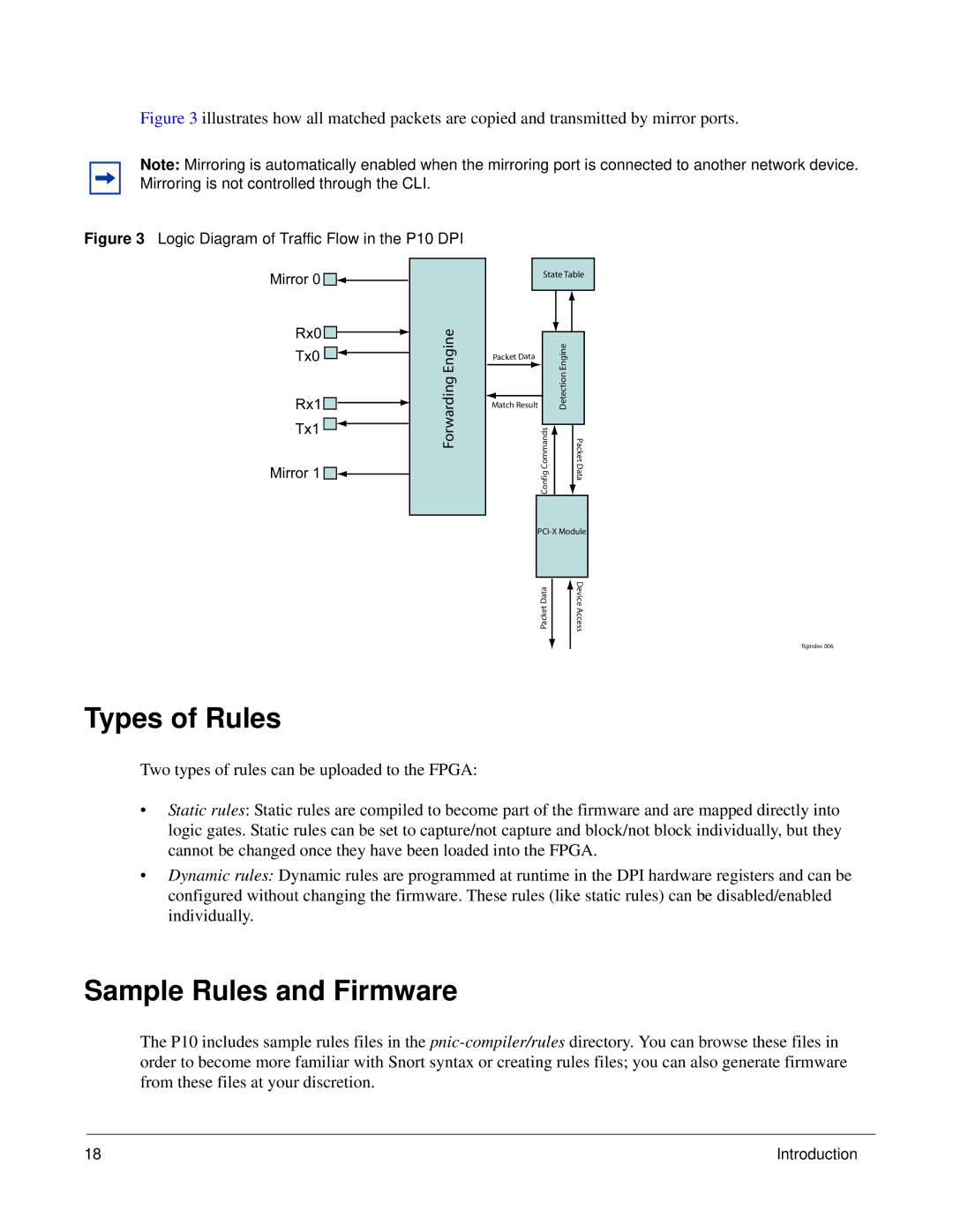
Figure 3 illustrates how all matched packets are copied and transmitted by mirror ports.
Note: Mirroring is automatically enabled when the mirroring port is connected to another network device. Mirroring is not controlled through the CLI.
Figure 3 Logic Diagram of Traffic Flow in the P10 DPI
Mirror 0 

Rx0 |
|
|
|
|
| Engine |
Tx0 |
|
|
|
|
| |
|
| |||||
|
|
|
|
| Forwarding | |
|
|
|
|
| ||
Rx1 |
|
|
|
|
| |
|
|
|
|
|
| |
|
|
|
|
|
| |
Tx1 |
|
|
|
|
|
|
|
|
|
|
|
| |
|
|
|
|
|
| |
|
|
|
|
|
|
Mirror 1 


Match Result
State Table
|
|
|
| Detection Engine | |
|
|
|
Config Commands |
| Packet Data |
| ||
|
| |
Packet Data
Device Access
figindex 006
Types of Rules
Two types of rules can be uploaded to the FPGA:
•Static rules: Static rules are compiled to become part of the firmware and are mapped directly into logic gates. Static rules can be set to capture/not capture and block/not block individually, but they cannot be changed once they have been loaded into the FPGA.
•Dynamic rules: Dynamic rules are programmed at runtime in the DPI hardware registers and can be configured without changing the firmware. These rules (like static rules) can be disabled/enabled individually.
Sample Rules and Firmware
The P10 includes sample rules files in the
18 | Introduction |
