Chapter 1 |
|
| Installation |
| ||
|
|
|
|
|
| |
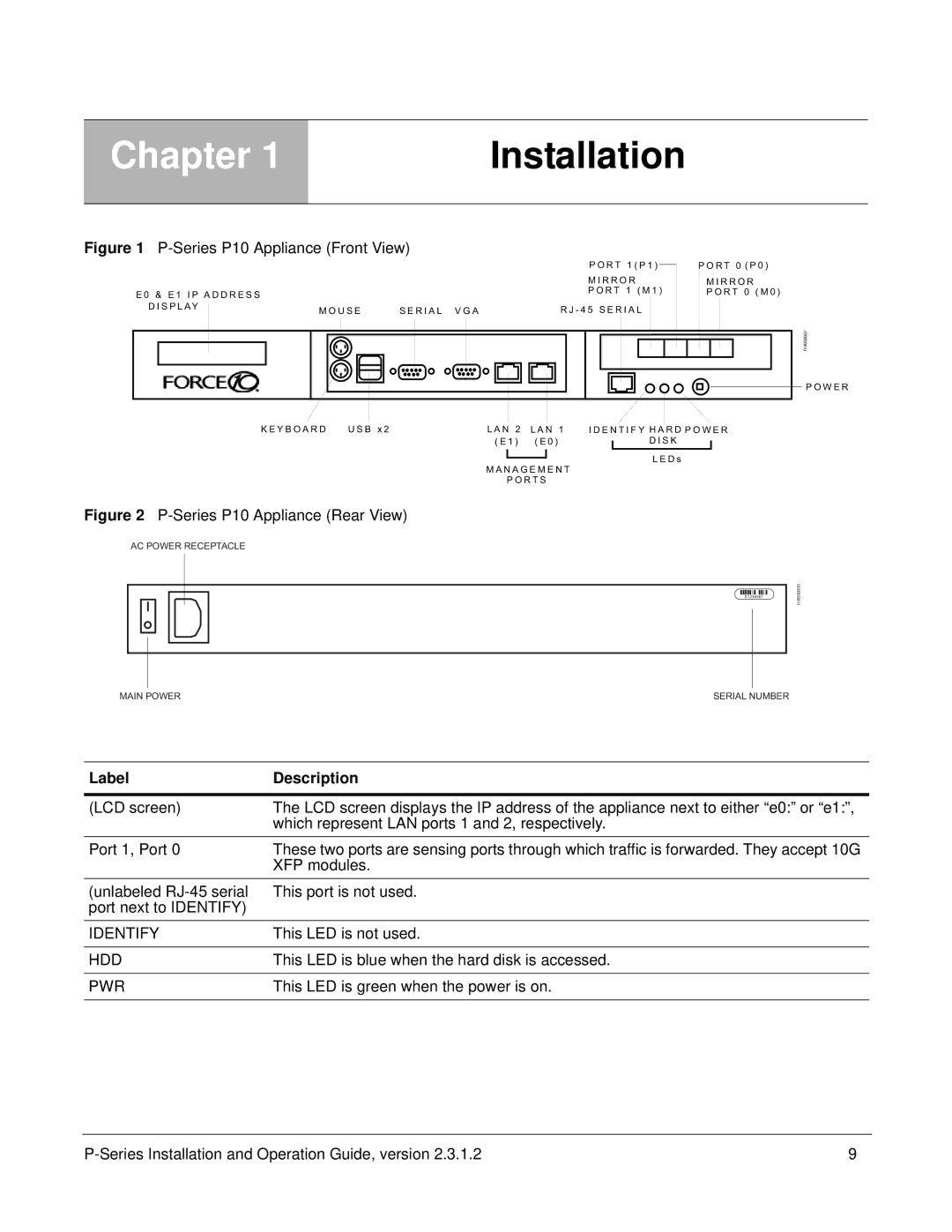
Figure 1 | P O R T 1 ( P 1 ) |
|
|
| ||
|
|
|
|
| P O R T 0 ( P 0 ) | |
|
|
|
| |||
|
|
| M I R R O R | M I R R O R | ||
E 0 & E 1 I P A D D R E S S |
|
| P O R T 1 ( M 1 ) | P O R T 0 ( M 0 ) | ||
D I S P L AY | M O U S E | S E R I A L V G A | R J - 4 5 S E R I A L |
| ||
|
| |||||
fn9000007
K E Y B O A R D | U S B x 2 | L A N 2 L A N 1 | I D E N T I F Y H A R D P O W E R | |||||
|
| ( E 1 ) ( E 0 ) |
| D I S K |
|
| ||
|
|
|
| |||||
|
|
|
|
|
| L E D s |
| |
|
| M A N A G E M E N T | ||||||
|
|
|
|
|
| |||
|
|
| P O R T S |
|
|
|
| |
Figure 2 P-Series P10 Appliance (Rear View)
AC POWER RECEPTACLE
01234567
P O W E R
fn9000009
MAIN POWER | SERIAL NUMBER |
Label | Description |
|
|
(LCD screen) | The LCD screen displays the IP address of the appliance next to either “e0:” or “e1:”, |
| which represent LAN ports 1 and 2, respectively. |
Port 1, Port 0 | These two ports are sensing ports through which traffic is forwarded. They accept 10G |
| XFP modules. |
(unlabeled | This port is not used. |
port next to IDENTIFY) |
|
IDENTIFY | This LED is not used. |
|
|
HDD | This LED is blue when the hard disk is accessed. |
|
|
PWR | This LED is green when the power is on. |
|
|
9 |