4. INSTALLING OPTIONAL EQUIPMENT
4.3DVI-RGB Conversion Kit (for VDR connection)
This information provides the procedure necessary for the installation of the
Name: |
| ||
Type: |
|
| |
Code no.: |
|
| |
Resolution: | Outputs RGB with the resolution of DVI input. | ||
| Display unit | Resolution | DIP switch setting |
| 1024x1280 | OFF | |
| 1024x1365 | ON | |
Output signal specification: | Video; | ||
|
| Horizontal sync signal; TTL level, negative polarity | |
|
| Vertical sync signal; TTL level, negative polarity | |
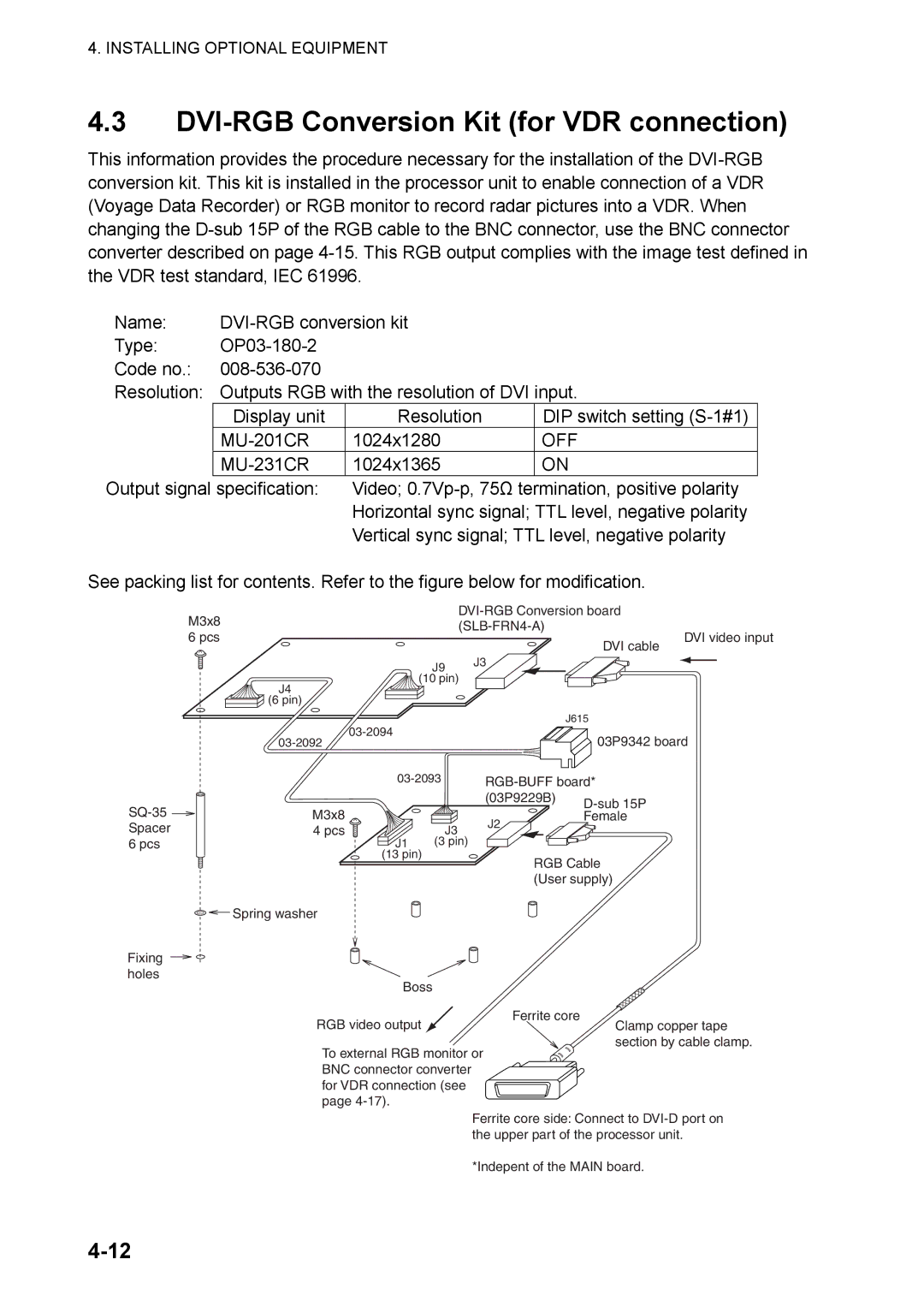
See packing list for contents. Refer to the figure below for modification.
M3x8 6 pcs
J4
![]() (6 pin)
(6 pin)
DVI cable
J9 J3
(10 pin)
J615
DVI video input
Fixing holes
M3x8 4 pcs
Spring washer
03P9342 board
|
| (03P9229B) | |
|
|
| |
| J3 | J2 | Female |
|
| ||
|
|
| |
J1 | (3 pin) |
|
|
(13 pin)
RGB Cable (User supply)
Boss
Ferrite core
RGB video output ![]() Clamp copper tape
Clamp copper tape
section by cable clamp.
To external RGB monitor or BNC connector converter
for VDR connection (see page
Ferrite core side: Connect to
*Indepent of the MAIN board.