4. INSTALLING OPTIONAL EQUIPMENT
Connection
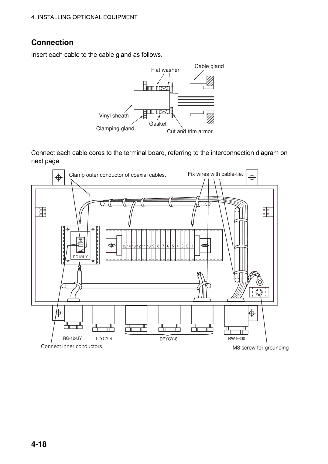
Insert each cable to the cable gland as follows.
Flat washer
Vinyl sheath
Gasket
Cable gland
Clamping gland
Cut and trim armor.
Connect each cable cores to the terminal board, referring to the interconnection diagram on next page.
Clamp outer conductor of coaxial cables.
Fix wires with
RG12/UY |
15 14 13 12 11 10 9 8 7 6 5 4 3 2 1
| |||
Connect inner conductors. |
| M8 screw for grounding | |
