Excel
72-2958
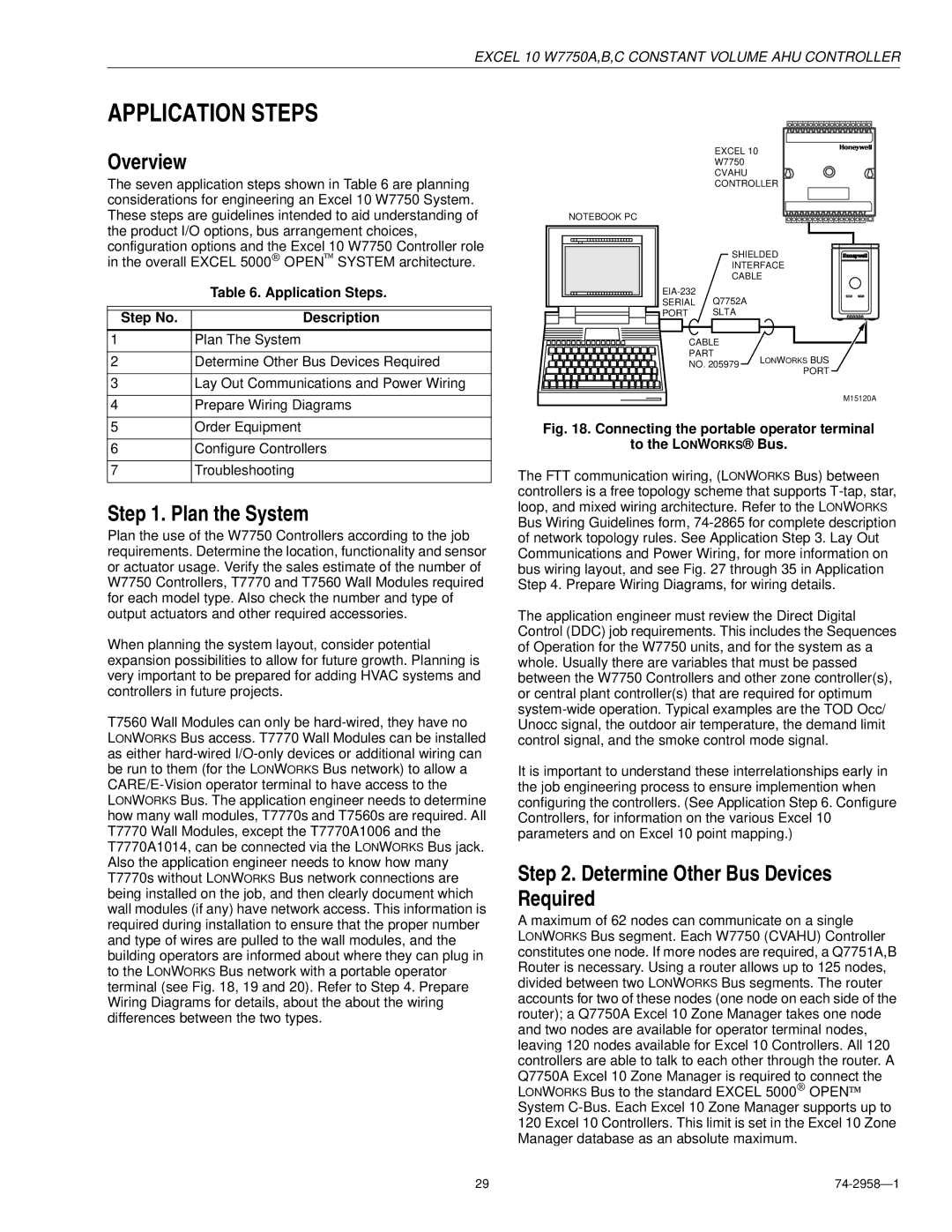
General Considerations W7750 Controllers
Appendices
74-2958
List of Figures
74-2958
Setpoint ramping parameters with ramp rate calculation
List of Tables
Typical system overview
Description of Devices
Control Provided
Control Application
Organization of Manual
Products Covered
Applicable Literature
Form No Title
Agency Listings
Product Names
Abbreviations and Definitions
Controllers
Construction
DI-1
W7750A
Special Note for the W7750B,C Unit
Performance Specifications
Power
Memory Capacity
Specified Space Temperature Sensing Range
CPU
Excel 10 W7750C Constant Volume AHU Controller
Jack
Lonmark Functional Profile
DIN rail adapters
Analog Inputs
Inputs/Outputs
Digital Outputs
Digital Inputs
Triac Outputs on the W7750B,C Models only
Duct Sensor
Wall Modules
T7770A1006
T7770C
T7560A,B construction in in. mm
General
Configurations
Configuration Options Summary For W7750A,B,C Controllers
Staged HEATING/COOLING Control
Allowable Heating and Cooling Equipment Configurations
Heat Pump Control
Modulating HEATING/COOLING Control
Pneumatic Actuator Control
Economizer Control
Window Open/Closed Digital Input
Occupancy Sensor
Wall Module Options
MIXED-OUTPUT-TYPE Control
Dirty Filter Monitor
Modes of Operation
Indoor Air Quality IAQ Override
Smoke Control
Disabled
OFF Mode
Not
Assigned
Plan the System
Overview
Determine Other Bus Devices Required
Step No Description
Lonworks Bus Layout
Lay Out Communications and Power Wiring
Excel VAV Cvahu
DeviceVA Information Obtained from
Power Wiring
Power Budget Calculation Example
ML6161A/B Damper Actuator, 35 lb-in R8242A Contactor
VA Ratings For Transformer Sizing Device Description
ML7984B PWM Valve Actuator
Line Loss
Nema class 2 transformer voltage output limits
Power wiring details for one Excel 10 per Transformer
General Considerations
Prepare Wiring Diagrams
W7750 Controllers
Terminal Terminal Number Description
Factory Default Digital Outputs
Constant Volume AHU Controller
ML6161 Floating Actuator COM CCW Load Controller Power Heat
Wall
Economizer Damper PWM Actuator Power Signal
W7750C Constant
Pneumatic transducer to W7750B,C Shown, see triangle note
Lonworks Bus Termination Module
Brown Orange
Order Equipment
Lonworks Bus termination wiring options
Sensor with Bypass/LED and Lonworks Jack
T7770 and T7560 Wall Modules
Honeywell Logo T7770D1018
Echelon Based Components and Parts
Accessories Sensors
Accessories
Troubleshooting
Configure Controllers
Troubleshooting Excel 10 Controllers and Wall Modules
Cabling
Resistance Value ohms
Alarms
Excel 10 Alarms
W7750 Controller Status LED
Broadcasting the Service Message
Setting the Pid Parameters
Appendix A. Using E-Vision to Commission a W7750 Controller
T7770C,D Wall Module Bypass Pushbutton and Override LED
Sensor Calibration
Appendix B. Sequences of Operation
Common Operations
Heating
Room Temperature Sensor RmTemp
Economizer
IAQ Option
Remote Setpoint RmtStptPot
Bypass Mode StatusOvrd and StatusLed
Setpoint Limits LoSetptLim and HiSetptLim
BypassTime
Occupancy Mode and Manual Override Arbitration
Continuous Unoccupied Mode
Not Assigned
Bypass Occupied
Time Clock OccTimeClock
Recovery Ramping for Heat Pump Systems
Schedule Master SchedMaster
Setpoint Ramping
Smoke Control
Window Sensor StatusWndw
FAN Operation
Demand Limit Control DLC
Dirty Filter Monitor
Temperature Control Operations
See for a diagram of a typical W7750 Unit
ONE Stage
Staged Cooling Control
TWO Stages
Three Stages
Series 60 Modulating Control
Cascade Control of Modulating COOLING/HEATING
Pulse Width Modulating PWM Control
Outdoor AIR Lockout of HEATING/COOLING
Indoor AIR Quality IAQ Override
Economizer ENABLE/DISABLE Control
Freeze Stat
Discharge AIR LOW Limit Control
Control Parameters Address
Input Output Points Address
Energy Management Points Address
Status Points Address
Mappable User Addresses and Table Number
Air Flow
Relative Temperature
CO2 Concentration
Enthalpy
Placed in manual mode through a menu
Application reset therefore, these points can
Valid states and the corresponding
Enumerated values are shown
Input/Output Points
Default
NvName Field Name
Comments
Occsensor Shcedmasterin
NciIoSelect DigitalIn1
255 NciIoSelect DigitalIn2
Occsensor Unuseddi
COOLSTAGE2
COOLSTAGE1
COOLSTAGE3
COOLSTAGE4
Siinvalid
Sixtyfifty
True
PPM Siinvalid
False
Position when poor indoor air quality is detected
EconEnSw NvoIO EconEnableIn
StatusDI3 NvoIO UbDigitalIn
OccSensr NvoIO
NvName
Default Comments
Control Parameters
MaxClRamp NciAux1SetPt UbMaxClRampS0 Degrees F/Hr
OdEnthalpyEnable
MinClRamp NciAux1SetPt UbMinClRampS0 Degrees F/Hr
MaxClRamp, OdTempMaxClRamp,
PPM
GainCoolProp NciAux2SetPt UbKpCoolS2 Degrees F Degrees C
Discharge air temperature cascade control loop
Gain for the cooling control loop
GainHeatProp NciAux2SetPt UbKpHeatS2 Degrees F Degrees C
Energy Management Points
NviFree1 Value
Refer to WSHPEnable.value
Auxiliary functions. nviFree1 controls the FREE1OUT
Network variable input fails
DestTimeClk NviTimeClk State
NviTimeClk Value
Refer to nviTimeClk.value
255 SrcTimeClkCt NvoTimeClk Value
Status Points
Bit Offset = SensorFailAlrm
Alarmbit1
Bit Offset = FrostProtectAlrm
Bit Offset = InvalidSetPtAlrm
Nodedisabled
Noalarm
Smokealarm
Updateallfields
Startupwait
Disabledmode
Heat
Cool
Air flow switch is configured
StatusEconEn NvoData1 EconEnable
NciAux1SetPts.ubOdEnthalpyEnableS2
StatusManOcc NvoData1 NetManOcc
Auxiliary heating stages are turned on
HeatStgsOn NvoData1 HeatStagesOn
CoolStgsOn NvoData1 CoolStagesOn
For both heating or cooling
NciConfig.SmokeControl
Is 1, the algorithm controls as per the settings found
Controller mode is switched to Freezeprotect
MonitorSw NvoData1 MonSwitch
Tempcontrolptfield
Bypasstimerfield
Spacetempfield
Dischargetempfield
Ubinvalid
SpaceTempError
StatusError NvoError Errorbit0
NvoError Errorbit0
Bit Offset = Temperature SetPtError NvoError Errorbit0
Bit Offset = RtnEnthalpyError NvoError Errorbit1
NvoError Errorbit1
Are disabled as if the sensor was not configured
Bit Offset = SpaceCO2Error NvoError Errorbit1
Bit Offset = NvDlcShedError NvoError Errorbit2
Bit Offset = NvWindowError NvoError Errorbit2
Bit Offset = NvTodEventError NvoError Errorbit3
Bit Offset = NvByPassError NvoError Errorbit3
Cfgexternal
Cfglocal
Cfgnul
Calibration Points
Configuration Parameters
False True
DisMinClTime NciConfig DisableCoolMinTime
DisMinHtTime NciConfig DisableHeatMinTime
CascCntrl NciConfig CascadeControl
UseRaTempCtl NciConfig
Offset Absolutemiddle
Last NET
None Normal
Bypassonly
Lonmark /Open System Points
Hvacheat
Hvacauto
Hvacmrngwrmup Hvacprecool Hvaccool Hvacnightpurge Hvacnul
Hvacoff
DestRmTemp NviSpaceTemp Degrees F
74-2958 100
SNVTtempp 14 to
SrcRmTemp NvoSpaceTemp Degrees F
Hvactest
Hvacauto Hvacnul
Hvacmrngwrmup
Alarmnotifydisabled
103 NvoStatus Inalarm
NvoStatus Electricalfault
255 Not configured 74-2958
NvoStatus Unabletomeasure
Swon
Corresponding economizer function is not enabled because
On other nodes. If the economizer function is configured by
SrcEconEnable NvoEcon State
SrcEconEnCt NvoEcon Value
Direct Access And Special Points
OFF
Data Share Points
=using One-to-Many and not using points
Approximate Memory Size Estimating Procedure
= including mapped points and others for
Mapped points = number of mapped points per Excel
Resistance Sensors
Sensor Resistance Versus Temperature Resistance Ohms
Sensor Type
Sensor Use
Direct Setpoint Temperature
Offset Setpoint Temperature
T7770B,C 10K ohm setpoint potentiometer Relative
Above and Below Setpoint Resistance Ohms
Sensor Voltage Versus Humidity Relative Humidity Percentage
Voltage/Current Sensors
Sensor Voltage Versus Humidity Humidity Percentage
113 74-2958
Sensor Current Versus Enthalpy volts Enthalpy mA
MAmAmAmA AmA mA mA
T7242 or equivalent
74-2958 114
Sensor Voltage Versus Input Voltage To A/D Voltage to A/D
Pressure Inw kPa Sensor Voltage Vdc
Sensor Voltage Vdc Versus Pressure Inw
Inw
50.0.13