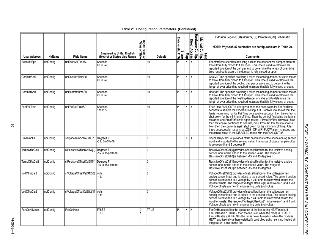
Table 25. Configuration Parameters. (Continued)
|
|
|
|
|
|
|
|
|
|
|
|
|
|
|
|
|
|
|
|
| Value | Digital |
|
|
| Direct | Hardware | Manual |
| NOTE: Physical I/O points that are configurable are in Table 20. | |
|
|
|
|
|
|
|
|
|
|
|
|
|
|
| |
| User Address | NvName | Field Name | (Metric) or States plus Range | ofState | Stateor | Default | (M, P,S) | Share | Map | Access | Config. | Config. | Test | Comments |
|
|
|
| Engineering Units: English |
|
|
|
|
|
|
|
|
|
|
|
| EconMtrSpd | nciConfig | ubEconMtrTimeS0 | Seconds |
|
| 90 | P |
| X | X |
|
|
| EconMtrTime specifies how long it takes the economizer damper motor to |
|
|
|
| 20 to 240 |
|
|
|
|
|
|
|
|
|
| travel from fully closed to fully open. This time is used to calculate the |
|
|
|
|
|
|
|
|
|
|
|
|
|
|
| reported position of the damper and to determine the length of over drive |
|
|
|
|
|
|
|
|
|
|
|
|
|
|
| time required to assure the damper is fully closed or open. |
|
|
|
|
|
|
|
|
|
|
|
|
|
|
|
|
| CoolMtrSpd | nciConfig | ubCoolMtrTimeS0 | Seconds |
|
| 90 | P |
| X | X |
|
|
| CoolMtrTime specifies how long it takes the cooling damper or valve motor |
|
|
|
| 20 to 240 |
|
|
|
|
|
|
|
|
|
| to travel from fully closed to fully open. This time is used to calculate the |
|
|
|
|
|
|
|
|
|
|
|
|
|
|
| reported position of the cooling damper or valve and to determine the |
|
|
|
|
|
|
|
|
|
|
|
|
|
|
| length of over drive time required to assure that it is fully closed or open. |
|
|
|
|
|
|
|
|
|
|
|
|
|
|
|
|
| HeatMtrSpd | nciConfig | ubHeatMtrTimeS0 | Seconds |
|
| 90 | P |
| X | X |
|
|
| HeatMtrTime specifies how long it takes the heating damper or valve motor |
|
|
|
| 20 to 240 |
|
|
|
|
|
|
|
|
|
| to travel from fully closed to fully open. This time is used to calculate the |
|
|
|
|
|
|
|
|
|
|
|
|
|
|
| reported position of the heating damper or valve and to determine the |
|
|
|
|
|
|
|
|
|
|
|
|
|
|
| length of over drive time required to assure that it is fully closed or open. |
|
|
|
|
|
|
|
|
|
|
|
|
|
|
|
|
| FanFailTime | nciConfig | ubFanFailTimeS0 | Seconds |
|
| 10 | P |
| X | X |
|
|
| Each time FAN_OUT is energized, then the node waits for FanFailTime |
|
|
|
| 1 to 255 |
|
|
|
|
|
|
|
|
|
| seconds to sample the ProofAirFlow input. If ProofAirFlow shows that the |
|
|
|
|
|
|
|
|
|
|
|
|
|
|
| fan is not running for FanFailTime consecutive seconds, then the control is |
|
|
|
|
|
|
|
|
|
|
|
|
|
|
| shut down for the minimum off time. Then the control (including the fan) is |
|
|
|
|
|
|
|
|
|
|
|
|
|
|
| restarted and ProofAirFlow is again tested. If ProofAirFlow shows air flow, |
95 |
|
|
|
|
|
|
|
|
|
|
|
|
|
| then the control continues to operate, but if ProofAirFlow fails to show air |
|
|
|
|
|
|
|
|
|
|
|
|
|
| flow, then the control is again shut down for the minimum off time. After | |
|
|
|
|
|
|
|
|
|
|
|
|
|
|
| three unsuccessful restarts, a LOSS_OF_AIR_FLOW alarm is issued and |
|
|
|
|
|
|
|
|
|
|
|
|
|
|
| the control stays in the DISABLED mode with the FAN_OUT off. |
|
|
|
|
|
|
|
|
|
|
|
|
|
|
|
|
| RmTempCal | nciConfig | siSpaceTempZeroCalS7 | Degrees F |
|
| 0 |
|
| X | X |
|
|
| SpaceTempZeroCal provides offset calibration for the space analog sensor |
|
|
|
|
|
|
|
|
|
|
|
|
|
| input and is added to the sensed value. The range of SpaceTempZeroCal | |
|
|
|
|
|
|
|
|
|
|
|
|
|
|
| is between |
|
|
|
|
|
|
|
|
|
|
|
|
|
|
|
|
| TempOffstCal1 | nciConfig | siResistiveOffsetCalS7[0] | Degrees F |
|
| 0 |
|
|
|
|
|
|
| ResistiveOffsetCal[0] provides offset calibration for the resistive analog |
|
|
|
|
|
|
|
|
|
|
|
|
|
| sensor input and is added to the sensed value. The range of | |
|
|
|
|
|
|
|
|
|
|
|
|
|
|
| ResistiveOffsetCal[0] is between |
|
|
|
|
|
|
|
|
|
|
|
|
|
|
|
|
| TempOffstCal2 | nciConfig | siResistiveOffsetCalS7[1] | Degrees F |
|
| 0 |
|
|
|
|
|
|
| ResistiveOffsetCal[1] provides offset calibration for the resistive analog |
|
|
|
|
|
|
|
|
|
|
|
|
|
| sensor input and is added to the sensed value. The range of | |
|
|
|
|
|
|
|
|
|
|
|
|
|
|
| ResistiveOffsetCal[1] is between |
|
|
|
|
|
|
|
|
|
|
|
|
|
|
|
|
| VoltOffstCal1 | nciConfig | siVoltageOffsetCalS12[0] | volts |
|
| 0 |
|
|
|
|
|
|
| VoltageOffsetCal[0] provides offset calibration for the voltage/current |
|
|
|
|
|
|
|
|
|
|
|
|
|
| analog sensor input and is added to the sensed value. The current analog | |
|
|
|
|
|
|
|
|
|
|
|
|
|
|
| sensor is converted to a voltage by a 249 ohm resister wired across the |
|
|
|
|
|
|
|
|
|
|
|
|
|
|
| input terminals. The range of VoltageOffsetCal[0] is between |
|
|
|
|
|
|
|
|
|
|
|
|
|
|
| Voltage offsets are new in engineering units (not volts). |
|
|
|
|
|
|
|
|
|
|
|
|
|
|
|
|
| VoltOffstCal2 | nciConfig | siVoltageOffsetCalS12[1] | volts |
|
| 0 |
|
|
|
|
|
|
| VoltageOffsetCal[1] provides offset calibration for the voltage/current |
|
|
|
|
|
|
|
|
|
|
|
|
|
| analog sensor input and is added to the sensed value. The current analog | |
|
|
|
|
|
|
|
|
|
|
|
|
|
|
| sensor is converted to a voltage by a 249 ohm resister wired across the |
|
|
|
|
|
|
|
|
|
|
|
|
|
|
| input terminals. The range of VoltageOffsetCal[1] is between |
|
|
|
|
|
|
|
|
|
|
|
|
|
|
| Voltage offsets are new in engineering units (not volts). |
|
|
|
|
|
|
|
|
|
|
|
|
|
|
|
|
| FanOnHtMode | nciConfig | FanOnHeat | FALSE | 0 |
| TRUE | P |
| X | X |
|
|
| FanOnHeat specifies the operation of the fan during HEAT mode. If |
|
|
|
| TRUE | 1 |
|
|
|
|
|
|
|
|
| FanOnHeat is 1(TRUE), then the fan is on when the mode is HEAT. If |
74 |
|
|
|
|
|
|
|
|
|
|
|
|
|
| FanOnHeat is a 0 (FALSE) the fan is never turned on when the mode is |
|
|
|
|
|
|
|
|
|
|
|
|
|
| HEAT, and typically a thermostatically controlled switch sensing heated air | |
- |
|
|
|
|
|
|
|
|
|
|
|
|
|
| temperature turns on the fan. |
2958— 1 |
|
|
|
|
|
|
|
|
|
|
|
|
|
| |
|
|
|
|
|
|
|
|
|
|
|
|
|
|
| |
|
|
|
|
|
|
|
|
|
|
|
|
|
|
|
![]()
![]() EXCEL 10 W7750A,B,C CONSTANT VOLUME AHU CONTROLLER
EXCEL 10 W7750A,B,C CONSTANT VOLUME AHU CONTROLLER