EXCEL 10 W7750A,B,C CONSTANT VOLUME AHU CONTROLLER
Occasionally, the PID parameters require tuning to optimize comfort and smooth equipment operation. This applies to the W7750A,B,C Controllers.
CVAHU Controllers are configured by
lists some recommended values to use as a starting point. These recommended values are based on past experience with the applications and in most cases do not require further adjustment.
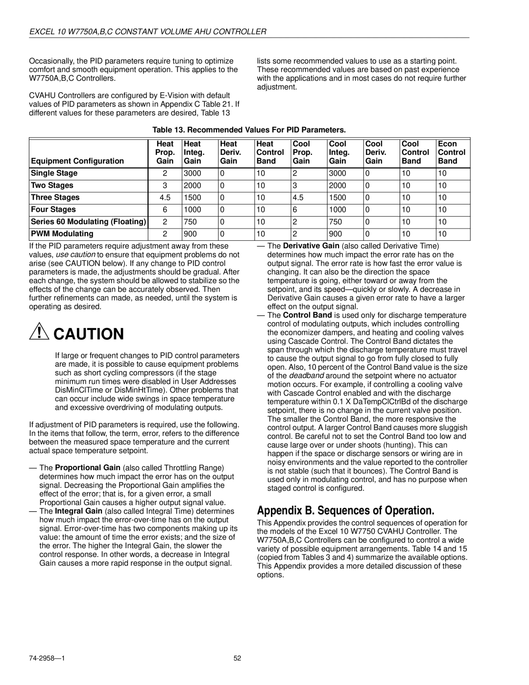
Table 13. Recommended Values For PID Parameters.
|
|
|
|
|
|
|
|
|
|
| Heat | Heat | Heat | Heat | Cool | Cool | Cool | Cool | Econ |
| Prop. | Integ. | Deriv. | Control | Prop. | Integ. | Deriv. | Control | Control |
Equipment Configuration | Gain | Gain | Gain | Band | Gain | Gain | Gain | Band | Band |
|
|
|
|
|
|
|
|
|
|
Single Stage | 2 | 3000 | 0 | 10 | 2 | 3000 | 0 | 10 | 10 |
|
|
|
|
|
|
|
|
|
|
Two Stages | 3 | 2000 | 0 | 10 | 3 | 2000 | 0 | 10 | 10 |
|
|
|
|
|
|
|
|
|
|
Three Stages | 4.5 | 1500 | 0 | 10 | 4.5 | 1500 | 0 | 10 | 10 |
|
|
|
|
|
|
|
|
|
|
Four Stages | 6 | 1000 | 0 | 10 | 6 | 1000 | 0 | 10 | 10 |
|
|
|
|
|
|
|
|
|
|
Series 60 Modulating (Floating) | 2 | 750 | 0 | 10 | 2 | 750 | 0 | 10 | 10 |
|
|
|
|
|
|
|
|
|
|
PWM Modulating | 2 | 900 | 0 | 10 | 2 | 900 | 0 | 10 | 10 |
|
|
|
|
|
|
|
|
|
|
If the PID parameters require adjustment away from these values, use caution to ensure that equipment problems do not arise (see CAUTION below). If any change to PID control parameters is made, the adjustments should be gradual. After each change, the system should be allowed to stabilize so the effects of the change can be accurately observed. Then further refinements can made, as needed, until the system is operating as desired.
![]() CAUTION
CAUTION
If large or frequent changes to PID control parameters are made, it is possible to cause equipment problems such as short cycling compressors (if the stage minimum run times were disabled in User Addresses DisMinClTime or DisMinHtTime). Other problems that can occur include wide swings in space temperature and excessive overdriving of modulating outputs.
If adjustment of PID parameters is required, use the following. In the items that follow, the term, error, refers to the difference between the measured space temperature and the current actual space temperature setpoint.
—The Proportional Gain (also called Throttling Range) determines how much impact the error has on the output signal. Decreasing the Proportional Gain amplifies the effect of the error; that is, for a given error, a small Proportional Gain causes a higher output signal value.
—The Integral Gain (also called Integral Time) determines how much impact the
—The Derivative Gain (also called Derivative Time) determines how much impact the error rate has on the output signal. The error rate is how fast the error value is changing. It can also be the direction the space temperature is going, either toward or away from the setpoint, and its speed— quickly or slowly. A decrease in Derivative Gain causes a given error rate to have a larger effect on the output signal.
—The Control Band is used only for discharge temperature control of modulating outputs, which includes controlling the economizer dampers, and heating and cooling valves using Cascade Control. The Control Band dictates the span through which the discharge temperature must travel to cause the output signal to go from fully closed to fully open. Also, 10 percent of the Control Band value is the size of the deadband around the setpoint where no actuator motion occurs. For example, if controlling a cooling valve with Cascade Control enabled and with the discharge temperature within 0.1 X DaTempClCtrlBd of the discharge setpoint, there is no change in the current valve position. The smaller the Control Band, the more responsive the control output. A larger Control Band causes more sluggish control. Be careful not to set the Control Band too low and cause large over or under shoots (hunting). This can happen if the space or discharge sensors or wiring are in noisy environments and the value reported to the controller is not stable (such that it bounces). The Control Band is used only in modulating control, and has no purpose when staged control is configured.
Appendix B. Sequences of Operation.
This Appendix provides the control sequences of operation for the models of the Excel 10 W7750 CVAHU Controller. The W7750A,B,C Controllers can be configured to control a wide variety of possible equipment arrangements. Table 14 and 15 (copied from Tables 3 and 4) summarize the available options. This Appendix provides a more detailed discussion of these options.
| 52 |