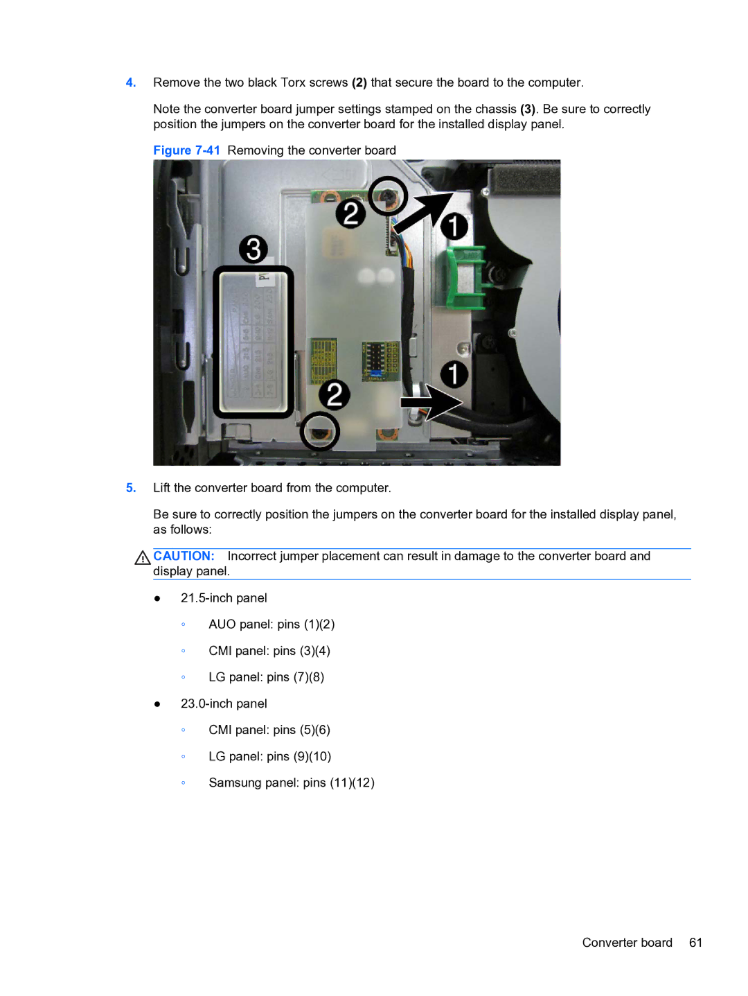
4.Remove the two black Torx screws (2) that secure the board to the computer.
Note the converter board jumper settings stamped on the chassis (3). Be sure to correctly position the jumpers on the converter board for the installed display panel.
Figure 7-41 Removing the converter board
5.Lift the converter board from the computer.
Be sure to correctly position the jumpers on the converter board for the installed display panel, as follows:
CAUTION: Incorrect jumper placement can result in damage to the converter board and display panel.
●21.5-inch panel
◦AUO panel: pins (1)(2)
◦CMI panel: pins (3)(4)
◦LG panel: pins (7)(8)
●
◦CMI panel: pins (5)(6)
◦LG panel: pins (9)(10)