Maintenance & Service Guide
Maintenance & Service Guide
About This Book
Iii
Iv About This Book
Table of contents
Serial ATA Sata Drive Guidelines and Features
Page
Restore and Recovery 133
General Requirements 192 Japanese Power Cord Requirements
Ethernet BNC 187
Country-Specific Requirements 193
Minitower models 194 Small form factor models 195
Installing and Customizing the Software
Installing the Operating System
Downloading Microsoft Windows Updates
Installing or Upgrading Device Drivers Windows systems
Accessing Disk Image ISO Files
Protecting the Software
HP Pro 2110 Computer Setup F10 Utilities
Computer setup utility differs for the different models
Using Computer Setup F10 Utilities
HP Pro 2110 Computer Setup F10 Utilities
Computer Setup-Main
Computer Setup F10 Utility
2Computer Setup-Main
Computer Setup-Advanced
3Computer Setup-Advanced
Computer Setup-Boot
4Computer Setup-Boot
Computer Setup-Power
5Computer Setup-Power
6Computer Setup-PC Health
Computer Setup-PC Health
Computer Setup-Exit
7Computer Setup-Exit
HP Pro 3120 Computer Setup F10 Utilities
System Date
8Computer Setup-Main
Option Description System Time
Language
3rd Drive
1st Drive
2nd Drive
4th Drive
9Computer Setup-Advanced
10Computer Setup-Power
11Computer Setup-Boot
Boot Priority
Priority
HP Pro 3125 Computer Setup F10 Utilities
12Computer Setup-Exit
13Computer Setup-Main
1st Drive
14Computer Setup-Advanced
Password Onboard Audio
SATA1 Controller
NX No Execute
15Computer Setup-Power
16Computer Setup-Boot
Technology
Computer Setup-Boot
17Computer Setup-Exit
HP Pro 3130 Computer Setup F10 Utilities
18Computer Setup-Main
1st Drive
19Computer Setup-Advanced
Password
Memory Size
20Computer Setup-Power
Onboard Video
Onboard
21Computer Setup-Boot
F10 Setup
22Computer Setup-Exit
Sata Hard Drive Cables
Serial ATA Hard Drive Characteristics
Sata Hard Drives
Sata Data Cable
Smart ATA Drives
Hard Drive Capacities
Page
Chassis Designation
Minitower
Minitower and small form factor chassis are available
Small Form Factor
Preventing Electrostatic Damage to Equipment
Electrostatic Discharge Information
Generating Static
Relative Humidity Event 55% 40% 10%
Static Shielding Protection Levels
Personal Grounding Methods and Equipment
Grounding the Work Area
Method Voltage
Operating Guidelines
Recommended Materials and Equipment
Cleaning the Keyboard
General Cleaning Safety Precautions
Cleaning the Computer Case
Routine Care
Cleaning the Mouse
Service Considerations
Cleaning the Monitor
Power Supply Fan
Screws
Cables and Connectors
Tools and Software Requirements
Hard Drives
Lithium Coin Cell Battery
Removal and Replacement Procedures Minitower MT Chassis
Preparation for Disassembly
Access Panel
Front Bezel
DDR3-SDRAM DIMMs
Bezel Blanks
Memory
Model Number Maximum Memory
Page
Populating Dimm Sockets
Dimm Socket Locations HP Pro
Dimm Socket Locations HP Pro
Description Socket Color Insertion Order
5DIMM Socket Locations HP Pro Memory
Dimm Socket Locations HP Pro
6DIMM Socket Locations HP Pro
Installing Memory Modules
Page
Expansion Cards
Expansion Slot Locations
9Expansion Slot Locations HP Pro
Expansion Slot Locations
13Removing a PCI Express x1 Expansion Card Expansion Cards
Page
Page
Cable Management
Connector Name Connector Color Description
Cable Connections
ATX1
Drives
Drive Positions
Installing Additional Drives
System Board Connector System Board Label Color
5System Board Drive Connections HP Pro
19System Board Drive Connections HP Pro
6System Board Drive Connections HP Pro
20System Board Drive Connections HP Pro
7System Board Drive Connections HP Pro
Removing an Optical Drive
Removing an Internal 3.5-inch Hard Drive
Page
27Removing the Hard Drive Drives
Front I/O and USB Panel Housing Assembly
Power Switch/LED Assembly
Remove the optical drive Removing an Optical Drive on
System Fan
Heat sink assembly
Processor
Page
Page
9Model 3125 power supply cable connections
Power Supply
8Model 3120 power supply cable connections
10Model 3130 power supply cable connections
10Model 3130 power supply cable connections
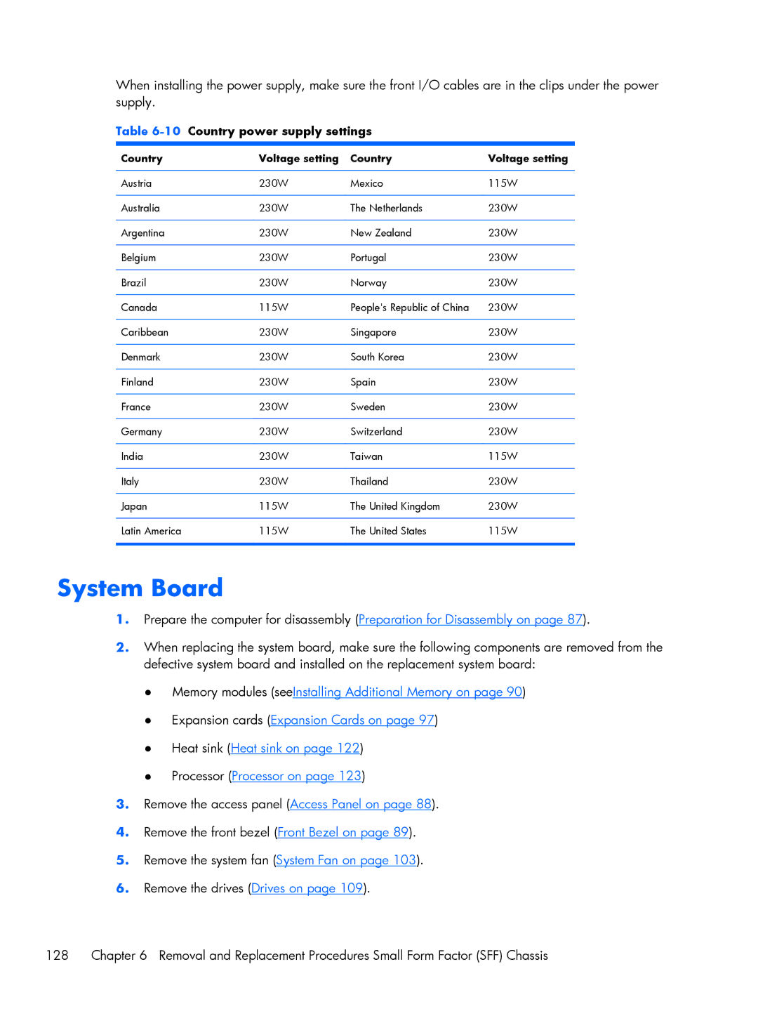
Country power supply settings
Country Voltage setting
11Country power supply settings
System Board
Page
Battery
Type 1 Battery Holder
Type 2 Battery Holder
Type 3 Battery Holder
Preparation for Disassembly
Access Panel
Front Bezel
Installing Additional Memory
DIMMs
3DIMM Socket Locations HP Pro
4DIMM Socket Locations HP Pro
Dimm Socket Locations HP Pro
5DIMM Socket Locations HP Pro
Installing DIMMs
Page
7Expansion Slot Locations HP Pro Expansion Cards
8Expansion Slot Locations HP Pro
4Expansion Slot Locations
12Removing a PCI or PCI Express x1 Expansion Card 100
Page
Page
System Fan
Cable Management
Atxpower
106
Optical Drive Eject Button
Page
19Drive Positions
5Drive Positions
Installing and Removing Drives
SATA3 not used
21System Board Drive Connections HP Pro
112
22System Board Drive Connections HP Pro
8System Board Drive Connections HP Pro
Removing the Hard Drive
Remove the optical drive Removing the Optical Drive on
28Hard drive screws
Front I/O Assembly
Page
Power Switch/LED Assembly
34Removing the power switch 120
Page
Heat sink
Processor
Page
Page
9HP Pro 2110, 3120, and 3130 power supply cable connections
Page
System Board
Page
Battery
Lift the battery out of its holder
40Removing the battery from a type 2 holder Battery
Page
Microsoft System Restore
System Recovery
System Recovery Options
System Recovery from the Windows Start Menu
System Recovery at System Startup
System Recovery from Recovery Discs
Recovery Discs
Choosing Recovery Discs
Creating Recovery Discs
Hewlett-Packard Vision Diagnostics
Accessing HP Vision Diagnostics
Survey Tab
Test Tab
Status Tab
Errors Tab
History Tab
Saving and Printing Information in HP Vision Diagnostics
Downloading the Latest Version of HP Vision Diagnostics
Help Tab
Click the Diagnostic link
Click the Download button
Troubleshooting Without Diagnostics
Safety and Comfort Before You Call for Technical Support
Helpful Hints
Page
Solving General Problems
Computer will not turn on or start Cause Solution
Click Start Task Manager
148 Troubleshooting Without Diagnostics
Computer shuts down automatically Cause Solution
Computer date and time display is incorrect Cause Solution
Cannot remove computer cover or access panel Cause Solution
Poor performance is experienced Cause Solution
150 Troubleshooting Without Diagnostics
Diskette drive cannot write to a diskette Cause Solution
Solving Diskette Problems
Diskette drive light stays on Cause Solution
Cannot format diskette Cause Solution
Diskette drive cannot read a diskette Cause Solution
152 Troubleshooting Without Diagnostics
Problem has occurred with a disk transaction Cause Solution
Invalid system disk message is displayed Cause Solution
Disk transaction problem Cause Solution
Solving Hard Drive Problems
Hard drive error occurs Cause Solution
Drive not found identified Cause Solution
Solving Media Card Reader Problems
154 Troubleshooting Without Diagnostics
Can not write to the media card Cause Solution
Solving Media Card Reader Problems 155
Computer’s software is used to safely eject the card
Solving Display Problems
156 Troubleshooting Without Diagnostics
Blank screen no video Cause Solution
Dim characters Cause Solution
Image is not centered Cause Solution
Select ImageControl/ Horizontal Position or Vertical
158 Troubleshooting Without Diagnostics
Out of Range displays on screen Cause Solution
Solving Audio Problems
Enable digital CD audio for this CD-ROM device is
160 Troubleshooting Without Diagnostics
Line-in jack is not functioning properly Cause Solution
Sound cuts in and out Cause Solution
Printer prints garbled information Cause Solution
Solving Printer Problems
Printer will not turn on Cause Solution
Printer is offline Cause Solution
Cursor will not move using the arrow keys on the keypad
Solving Keyboard and Mouse Problems
162 Troubleshooting Without Diagnostics
Cause Solution
Solving Keyboard and Mouse Problems 163
Optical mouse does not track cursor well Cause Solution
Click Start Control Panel Hardware
164 Troubleshooting Without Diagnostics
Cursor moves too fast or too slow Cause Solution
Sound Mouse
Solving Hardware Installation Problems
Solving Hardware Installation Problems 165
New device does not work Cause Solution
166 Troubleshooting Without Diagnostics
Click Hardware and Sound Click Device Manager
Solving Network Problems
168 Troubleshooting Without Diagnostics
Network status link light never flashes Cause Solution
Diagnostics reports a failure Cause Solution
New network card will not boot Cause Solution
Out of memory error Cause Solution
Solving Memory Problems
170 Troubleshooting Without Diagnostics
Memory count during Post is wrong Cause Solution
Solving CD-ROM and DVD Problems
Movie will not play in the DVD drive Cause Solution
172 Troubleshooting Without Diagnostics
Cannot eject compact disc tray-load unit Cause Solution
Try a different brand of media. Quality varies widely
USB flash drive not found identified Cause Solution
Solving USB Flash Drive Problems
174 Troubleshooting Without Diagnostics
System will not boot from USB flash drive Cause Solution
Solving Front Panel Component Problems
Solving Front Panel Component Problems 175
Solving Internet Access Problems
176 Troubleshooting Without Diagnostics
Unable to connect to the Internet Cause Solution
Click Network and Internet
Solving Internet Access Problems 177
Windows Vista
Click Internet Options
Click on Hardware and Sound
178 Troubleshooting Without Diagnostics
Click on System and Maintenance
Click on Device Manager
Solving Software Problems
Contacting Customer Support
1Numeric Codes and Text Messages
Post Text Messages
Post Text Messages
Control panel message Description Recommended action
2Diagnostic Audible Codes
Interpreting Post Diagnostic Audible Codes
Post Error Messages
Opened Warning item and select Clear
Duration of each beep or pause is defined below
Beep/Pause Type Action
Resetting the Password Jumper
Cmos
Clearing and Resetting the Cmos
Password Security and Resetting Cmos
Ethernet BNC
Connector and Icon Pin Signal
Connector and Icon 1/8 miniphone Pin Signal
Microphone
Headphone
Pin Power for CPU
Appendix a Connector Pin Assignments
Line-in Audio
Pin Signal
Pin Power
Connector
Signal Pin
X1, x4, x8, and x16 PCI Express Connector Pin a Signal
PCI Express
X1, x4, x8, and x16 PCI Express Connector Pin B Signal
Japanese Power Cord Requirements
General Requirements
Country-Specific Requirements
Country Accrediting Agency
Appendix C Specifications
Minitower models
Small form factor models
Rated Input Current maximum
HP Pro 105 106 Cable management
Country power cord set
193 Country power supply Settings
System Board 61, 62, 105
Locations 55 Power supply cable Connections
Locations Power supply cable Connections
System board drive Connectors HP Pro Dimm socket locations
176 Keyboard 162 Media Card Reader 154 Index
Resetting
Sata