When installing drives, follow these guidelines:

{The primary Serial ATA (SATA) hard drive must be connected to the dark blue primary SATA connector on the system board labeled SATA0.

{Connect secondary hard drives and optical drives to one of the light blue SATA connectors on the system board (labeled SATA1, SATA2, and SATA3).

{Connect a media card reader USB 3.0 cable with a USB 3.0 to USB 2.0 adapter to the USB 2.0 connector on the system board labeled MEDIA.

{The power cable for the drives has two branches coming off the system board connector. The first branch is a dual-headed cable with the first connector (four-wire) routed to the 3.5-inch optional drive bay and the second connector (two-wire) routed to the slim optical drive bay. The second branch is a dual-headed cable with the first connector routed to the 3.5-inch hard drive bay and the second connector routed to the 2.5-inch hard drive bay.

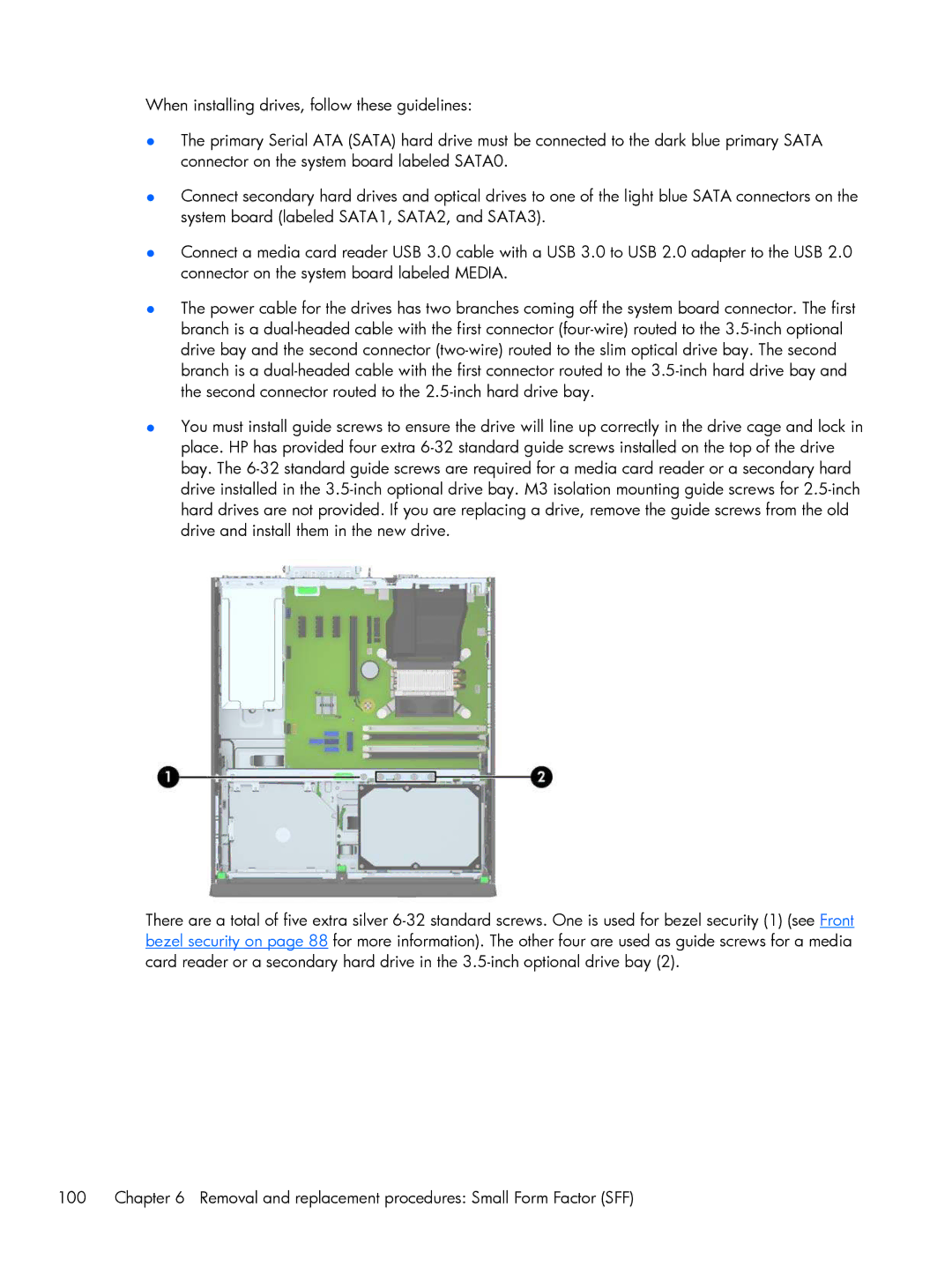
{You must install guide screws to ensure the drive will line up correctly in the drive cage and lock in place. HP has provided four extra 6-32 standard guide screws installed on the top of the drive bay. The 6-32 standard guide screws are required for a media card reader or a secondary hard drive installed in the 3.5-inch optional drive bay. M3 isolation mounting guide screws for 2.5-inch hard drives are not provided. If you are replacing a drive, remove the guide screws from the old drive and install them in the new drive.

There are a total of five extra silver 6-32 standard screws. One is used for bezel security (1) (see Front bezel security on page 88 for more information). The other four are used as guide screws for a media card reader or a secondary hard drive in the 3.5-inch optional drive bay (2).

100

Chapter 6 Removal and replacement procedures: Small Form Factor (SFF)